Pharmaceutical Engineering Long Question And Answers
Question 1. Explain the principles, construction, working, advantages, and disadvantages of ball mills.
Answer:
In a continuously operating ball mill, the feed material is fed through the central hole of one of the caps into the drum and moves there along, being exposed by grinding media.
- The material grinding occurs during impact falling grinding balls and abrasion of the particles between the balls.
- A ball mill also known as a pebble mill or tumbling mill is a milling machine that consists of a hollow cylinder containing balls; mounted on a metallic frame such that it can be rotated along its longitudinal axis.
- The balls which could be of different diameters occupy 30- 50 % of the mill volume and their size depends on the feed and mill size.
- The large balls tend to break down the coarse feed materials and the smaller balls help to form fine products by reducing void spaces between the balls. Ball mills grind material by impact and attrition.
The degree of milling in a ball mill is influenced by:
- The residence time of the material in the mill chamber.
- The size, density, and number of the balls.
- The nature of the balls (hardness of the grinding material)
- Feed rate and feed level in the vessel.
- Rotation speed of the cylinder.

Several types of ball mills exist. They differ to an extent in their operating principle. They also differ in their maximum capacity of the milling vessel, ranging from 0.010 liters for planetary ball mills, mixer mills, or vibration ball mills to several 100 liters for horizontal rolling ball mills.
Ball mill Uses:
- The small and average-capacity ball mills are used for the final grinding of drugs or grinding suspensions.
- The maximum capacity ball mills are used for milling ores before the manufacture of pharmaceutical chemicals
Ball mill Advantages:
- It produces very fine powder (particle size less than or equal to 10 microns).
- It is suitable for milling toxic materials since it can be used in a completely enclosed form.
- Has a wide application.
- It can be used for continuous operation.
- It is used in milling highly abrasive materials.
Ball mill Disadvantages:
- Contamination of product may occur as a result of wear and tear which occurs principally from the balls and partially from the casing.
- High machine noise level especially if the hollow cylinder is made of metal, but much less if rubber is used.
- Relatively long milling time.
- It is difficult to clean the machine after use.
Question 2. Define Flash distillation. Explain the principle and working of flash distillation.
Answer:
Flash Distillation:
Flash distillation is defined as a process in which the entire liquid mixture is suddenly vaporized (flash) by passing the feed from a high-pressure zone to a low-pressure zone. Flash distillation is also known as equilibrium distillation, i.e., separation is attempted when the liquid and vapor phases are in equilibrium. This method is frequently carried out as a continuous process and does not involve rectification.
Flash Distillation Principle:
When a hot liquid mixture is allowed to enter from a high-pressure zone into a low-pressure zone, the entire liquid mixture is suddenly vaporized. This process is known as flash vaporization. During this process, the chamber gets cooled.
The individual vapor phase molecules of high boiling fraction get condensed, while low boiling fraction remains as vapor. This process requires a certain amount of time. Therefore, the liquid and vapor are kept in intimate contact unit equilibrium is achieved. The liquid fraction is collected separately. The vapor is separated from the liquid and further allowed to condense.
Flash Distillation Uses:
- Flash distillation is used for separating components, which boil at widely different temperatures.
- It is widely used in the petroleum industry for refining crude oil.
Flash Distillation Advantages:
- Flash distillation is a continuous process.
- It is used for obtaining multi-component systems of narrow boiling range, especially in oil refineries.
- Examples are petroleum ether 60, 80, etc.
Flash Distillation Disadvantages:
- Flash distillation is not effective in separating components of comparable volatility.
- It is not suitable for two-component systems.
- It is not an efficient distillation when nearly pure components are required, because the condensed vapor and residual liquid are far from pure.
Flash Distillation Construction
The construction of a flash distillation consists of a pump, which is connected to a feed reservoir. Pump helps in pumping the feed into the heating chamber which contains a heating mechanism. The other end of the pipe is directly introduced into the vapor-liquid separator through a reducing valve. The vapor outlet is provided at the top of the separator and the liquid outlet is provided at the bottom.
Flash Distillation Working:
- The feed is pumped through a heater at a certain pressure. The liquid gets heated, which enters the vapor-liquid separator through a pressure-reducing valve.
- Due to the drop in pressure, the lid flashes, which further enhances the vaporization process. The sudden vaporization induces cooling. The individual vapor phase molecules of high boiling fraction get condensed, while low boiling fraction remains as vapor
- The mixture is allowed for a sufficient time so that vapor and liquid portions separate and achieve equilibrium.
- The vapor is separated through a pipe from above and liquid is collected from the bottom of the separator.

By continuously feeding into the still, it is possible to obtain continuous flash distillation. The operating conditions can be adjusted in such a way that the amount offered exactly equals the amount of material removed. Therefore, vapor and liquid concentrations at any point remain constant in the unit.
Question 3. Define drying. Discuss the theory of drying.
Answer:
Drying:
Drying is the process of removing water or other liquids from a material with the help of heat. The final product after drying is a dry solid or powder.
Drying Theory :
Drying is a complex operation involving transient transfer of heat and mass transfer. Sensible and latent heat must be transferred to the food to cause the water to evaporate. Physical changes that may occur include shrinkage, puffing, crystallization, and glass transitions.
In some cases, desirable or undesirable chemical or biochemical reactions may occur, leading to changes in color, texture, odor, and other properties of the solid product.
- The drying curve usually plots the drying rate versus drying time or moisture contents. Three major stages of drying can be observed in the drying curve.
- Transient early stage, during which the product is heated up.
- Constant rate period, in which moisture is comparatively easy to remove.
- Falling rate period, in which moisture is bound or held within the solid matrix

Constant rate:
- Sections B TO C of the curve, known as the constant rate periods, represent the removal of unbound water from the product. The surface of the product is very wet and the water activity is equal to one.
- In the constant rate period, the water is being evaporated effectively as a free water surface.
- The rate of removal of water can then be related to the rate of heat transfer, if there is no change in the temperature of the material and therefore all heat energy transferred to it must result in the evaporation of water.
Falling rate:
- The falling rate period is reached when the drying rate starts to decrease, and the surface water activity falls to less than one.
- At this point, there is not enough water on the surface to maintain a water activity value of one.
- The rate of drying is governed by the internal flow of liquid or vapor.
The falling rate period can be divided into two steps:
- First falling drying rate.
- Second falling drying rate.
- A fast falling drying rate occurs when wetted spots in the surface continually diminish until the surface is dried.
- The second falling rate occurs when wetted spots in the surface continually diminish until the surface is dried.
- The second falling rate period begins when the surface is completely dry and until the EMC is reached.
- Transport of moisture within the solid may occur by any one or more of the following mechanisms of mass transfer:
- Capillary flow
- Liquid diffusion, if the wet solid is at a temperature
below the boiling point of the liquid - Vapor diffusion, the liquid vaporizes within the material
- Knudsen diffusion, if drying takes place at very low
- temperatures and pressures.
- Surface diffusion
- Thermal diffusion
- Hydrostatic pressure differences, when internal vaporization rates exceed the rate of vapor transport through the solid to the surroundings.
- Combinations of the above mechanisms
Water activity:
It is defined as the chemical potential of the water present in a food’s ability to participate in chemical reactions. It is denoted as aw.
Ice at 0, -10,-20 and -50°C have the water activities of
1.00, 0.91, 0.82 and 0.62 respectively.
Mathematically, water activity is given as the ratio of the vapor pressure of water in a solution (ps) to the vapor pressure of pure water (pw).
Aw = ps/pw
Norrish equation (for aw at high moisture contents)
Log aw/xw = -k (1-xw)²
Where,
Xw = mole fraction of water in the food/ solution.
The values of constant k for various solutes in the Norrish equation for water activity of solutions have been found out.
Brunauer-Emmett- Teller (BET) equation at low moisture contents, aw between 0-0.45 or so:
Aw / M(1 – aw) = 1/M1C + (C – 1/ M1C)aw
Where,
M is the moisture of the commodity.
M1 is the moisture of a monomolecular layer.
C is a constant.
Question 4. Describe the construction, working, advantages, and disadvantages of Hammer mill.
Answer:
Hammer Mill Principle:
The hammer mill operates on the principle of impact between rapidly moving hammers mounted on a rotor and the powder material.
Hammer Mill Construction:
The hammer mill can be either the horizontal or the vertical shaft type. Hammers are usually made of hardened steel, and stainless steel with an impact surface made of extremely abrasive resistant material such as haustellate and carboy.
Stainless steel hammers are sufficient for pharmaceutical purposes.

Hammers may take several shapes. Two basic shapes of High speed are the stirrup and the bar.
- Bar-shaped hammers are used extensively in tablet granulation.
- The hammer blades can be with flat edges or sharp edges or both on each side.
- Hammers may be either rigid or swing-type.
- The free-swinging type has the advantage that there will be increasing clearance between hammers and screen if excessive build occurs in the mill.
- This unit is enclosed with a chamber containing a grid or removable screen through which the material must pass.
- These screens are not of woven type. Screens are prepared using metal sheets of varying thickness with perforated holes or slots.
Hammer Mill Working:
The hammers are allowed to be in continuous motion (8000 to 15000 revolutions per minute). The feed material is placed into the hopper, which flows vertically down and then horizontally, while hammers are in continuous motion.
These rotating hammers beat the material to yield smaller particles. Then, these particles pass through the screen. Due to the tangential exit, the size of the particles is considerably smaller than the aperture of the screen.
The screens are interchangeable so that any grade of fineness can be achieved. The hammers act as a centrifugal fan so that a large amount of air is drawn through the mill. In most cases, this is sufficient to counteract the heat generated during milling.
The fineness of the product can be regulated by altering:
- Rotor speed,
- Feed rate.
- Clearance between hammers and grinding plates,
- Number and type of hammers,
- Size of the discharge opening (screen)

Hammer Mill Uses:
- Fine to moderate grinding of powders may be obtained, depending on the speed of the hammer.
- The expected particle size may vary from 10 to 400 mm.
- Nonabrasive to moderately abrasive, brittle materials can be used as feedstock.
- It is used to mill dry materials, wet filter press cakes, ointments, slurries, etc.
- Brittle material is best fractured by impact from blunt hammers; fibrous material is best reduced in size by cutting edges.
Hammer Mill Advantages:
- Hammer mill is easy to set up (install), dismantle and clean up.
- Scale-up problems are minimal provided the same type of mill is used.
- Various types of feedstock can be handled using screens of different sizes.
- The hammer mill occupies a small space.
- It is versatile, i.e., speed and screen can be changed rapidly.
- As it is operated in a closed environment, dust can be reduced and explosion hazards can be prevented.
Hammer Mill Disadvantages:
- The screens may get clogged.
- Heat buildup during milling is more, therefore, product degradation is possible.
- Wearing of mill and screen is more with abrasive materials.
- Hammer mills cannot be employed to mill sticky, fibrous hard materials
Question 5. Define distillation. Explain the principle and working ofstem distillation.
Answer:
Distillation
Distillation is defined as the separation of the components of a liquid mixture by a process involving vaporization and subsequent condensation at another place.
The distillation process involves two steps:
- Converting a liquid into a vapor phase and
- Transferring the vapor to another place and recovering the liquid by condensation.
- The feed liquid is known as distilled. The condensed liquid is known as distillate or condensate.
Steam Distillation
Steam distillation is a method of distillation carried with the aid of steam and is used for the separation of high-boiling substances from non-volatile impurities.
High-boiling liquids cannot be purified by simple distillation, since the constituents in the mixture tend to decompose at higher temperatures. In such cases, steam distillation is employed. Steam distillation is used for the separation of immiscible liquids.
For substances, that are insoluble in water and not decomposed by heat, steam distillation provides an alternative to distillation under reduced pressure. Steam distillation is a common example of differential distillation.
Steam Distillation Principle:
A mixture of immiscible liquids begins to boil when the sum of their vapor pressures is equal to the atmospheric pressure.
- In the case of a mixture of water and turpentine, the mixture boils below the boiling point of pure water, though the turpentine boils at a much higher temperature than that of water.
- For example -The boiling point of turpentine is about 160°C.
- But when it is mixed with water and heated, the mixture boils at about 95.6°C.
- At this temperature, the vapor pressure of water is 86.245 kPa (647 mm Hg) and that of turpentine is 15.06 kPa (113 mm Hg).
- The sum of the vapor pressures is 101.31 kPa (760 mm Hg) which is normal atmospheric pressure. Thus, high boiling substances may be distilled at a temperature much below its boiling point, when water (steam) is used.
- For volatile substances, that are miscible with water, steam distillation involves the same principle as fractional distillation.
Steam Distillation Applications:
- Steam distillation is used for the separation of immiscible liquids.
- Examples: Toluene and Water.
- This method is used for extracting most of the volatile oils such as clove, anise, and eucalyptus.
- It is useful in the purification of liquid with a high boiling point
- For example: The essential oil of almonds.
- Camphor is distilled by this method.
- Aromatic waters are prepared by this method
Steam Distillation Advantages:
- Volatile oils can be separated at a lower temperature in steam distillation, without any decomposition and loss of aroma.
- If a substance has low volatility, it can be satisfactorily distilled, provided its molecular weight is considerably higher than water.
Steam Distillation Disadvantages:
- Steam distillation is not suitable when immiscible liquid & water react with each other.
Equipment Used on an Industrial Scale Construction:
It consists of a jacketed still with a perforated plate which forms a false bottom. Manholes are provided at the top and side for charging and discharging. A Florentine receiver is placed between the still and the condenser. The condenser is cooled by circulating cold water.

Steam Distillation Working:
- The material from which the volatile oil has to be extracted is placed in the still above the perforated plate.
- Steam is admitted to the jacket of the still. The water and material present in the still are heated to boiling. Simultaneously steam is also injected below the materials through a steam pipe from the jacket.
- The steam carries the volatile oil and gets condensed in the condenser, which is cooled by cold water. The condensate is collected into the Florentine receiver.
- Most volatile oils are lighter than water and well separated from the distillate as an upper layer and removed from the upper spout. The water can run off from the spout on the left and return to the still.
- Some volatile oils are heavier than water in which case the separation is reversed. Oil is collected from the lower spout.
Steam Distillation Variants:
- For volatile substances, that are miscible with water, the distillation method combines the principles of the steam and fractional distillations.
- If the specific gravity of the oil is near 1.0, then separation does not take place. In such cases, it may be necessary to collect the whole of the distillate.
- Further, it is extracted with a (volatile) organic solvent. The solvent should be distilled off to get the volatile oil.
Question 6. Describe the principle, construction, working, advantages, and disadvantages of a ribbon blender mixer with the help of a neat labeled diagram.
Answer:
Ribbon Blender Principle:
The mechanism of mixing is shear. Shear is transferred to the powder bed by moving blades (ribbon-shaped) in a fixed (non-movable) shell. High shear rates are effective in breaking lumps and aggregates. Convective mixing also occurs as the powder bed is lifted and allowed to cascade to the bottom of the container. An equilibrium state of mixing can be achieved.
Ribbon Blender Construction:
It consists of a non-movable horizontal cylindrical trough (shell) usually open at the top. It is fitted with two helical blades, which are mounted on the same shaft through the long axis of the trough. The blades have both right and left-hand twists. The blades are connected to a fixed-speed drive. The ribbon blender is top-loading with a bottom discharge spout. The trough can be closed with a lid.
Ribbon Blender Working:
Through the fixed-speed drive, ribbons are allowed to rotate. One blade moves the solids slowly in one direction and the other moves them quickly in the opposite direction.
- Different powders are introduced from the top of the trough. The body is covered because considerable dust may be evolved during dry blending and granulating solution may evaporate during wet granulation.
- The powders are lifted by a centrally located vertical screw and allowed to cascade to the bottom of the container (tumbling action).
- The counteracting blades set up high shear and are effective in breaking up lumps or aggregates
- Helical blades move the powders from one end to another.
- The final stage of the mix represents an equilibrium state. The operating conditions of a given mixer can markedly affect the steady state and thus the quality of the mixing, the blend is discharged from the bottom opening.
Ribbon Blender Uses:
- A ribbon blender is used to mix finely divided solids, wet solid mass, and sticky and plastic solids.
- Uniform size and density material can be easily mixed.
- It is used for liquid-solid and solid-solid mixing
Ribbon Blender Advantages:
- High shear can be applied using perforated baffles which bring about rubbing and breaking of aggregates.
- Headroom requirement is less.
Ribbon Blender Disadvantages:
- It is a poor mixer because the movement of particles is two-dimensional.
- Shearing action is less than in a planetary mixer.
- Dead spots (areas that remain unmixed) are observed in the mixer, though they are minimal.
- It is having speed drive

Question 7. Describe the construction, working, advantages, and disadvantages of a fluid energy mill.
Answer:
Energy mill Principle:
Fluid energy mill operates on the principle of impact and attrition. In this equipment, the feedstock is suspended within a high-velocity air stream. Milling takes place because of high-velocity collisions between the suspended particles.
Energy mill Construction:
The fluid energy mill consists of an elliptical pipe, which has a height of about 2 meters and a diameter ranging from 20 to 200 millimeters. The mill surface may be made of either soft stainless steel or tough ceramics. Usually, mills are constructed such that the contact surfaces are merely linings, which can be removed or replaced if excessively loaded after use.
- Grinding nozzles (usually two to six) may be placed tangential and/or opposed to the initial flow path of a powder. Normally, compressed air of 600 kilopascals to
- 1.0 megapascal is used. Inert gases can be used to minimize or eliminate the oxidation of susceptible compounds.
- A Venturi feeder is provided in the path of the airflow. An outlet with a classifier (cyclone separator or bag filter) is fitted to allow the escape of air.

Energy mill Working:
Powder is introduced through the inlet venturi. The air entering through the grinding nozzles transports the powder in the elliptical or circular track of the mill.
- In the turbulent stream of air, the suspended particles collide with each other and break.
- Thus, impact and attrition forces operate in size reduction. The resultant small particles (entrapped by air) are carried to the outlet and removed by cyclone separator or bag filters.
- The coarser particles undergo re-circulation in the chamber on account of their weight.
- These re-circulated particles collide again with new in¬ coming feedstock particles. The powder remains in the mill.
- Until its size is reduced sufficiently. Later it leaves via the sieve. Hence, a fluid energy mill produces particles with a narrow size distribution.
- Sometimes the particles, which are entrapped by the drag of gas, leave the mill and are carried out to a cyclone separator or bag collector for size separation.
Energy mill Uses:
A fluid energy mill is used to reduce the particle size of most drugs such as antibiotics and vitamins. When strict quality control is desirable for better absorption (bioavailability), this mill is the preferred one.
Ultrafine grinding can be achieved: Moderately hard materials can be processed for size reduction.
Energy mill Advantages:
- It has no moving parts, hence, heat is not produced during milling. Therefore, heat-labile substances can be milled.
- Examples are sulphonamides, vitamins, and antibiotics.
- Due to the expansion of gases under pressure cooling effect is produced during milling.
- It is a rapid and efficient method for reducing powders to 30 mm or less.
- Since there is no wear of the mill, contamination is not possible.
Energy mill Disadvantages:
- The energy mill is not suitable for milling soft, tacky, and fibrous materials.
- The equipment is expensive because it needs additional accessories particularly fluid energy source and dust collection equipment.
Question 8. Derive an equation for heat transmission through a metal wall from Fourier’s law. Write the applications of thermal conductivities.
Answer:
Fourier’s Law-Conduction of Heat through a Metal Wall Fourier’s law states that the rate of heat flow through a uniform material is proportional to the area and the temperature drop and inversely proportional to the length of the path of flow.
The Fourier’s law may be mathematically expressed as
Rate of heat flow an area (m²) × Temperature difference (Δr) / Thickness (m)
q A . ΔE / L (Or)
q = kmA. Δt/L ………….(1)
Where km = mean proportionality constant, W/m.K.
Derivation Fourier’s law can be applied to a metal wall through which the conduction of heat is taking place (Figure 5-1). The characteristics are as follows.
Area of the wall = A, m²
Thickness of the wall = L,m
The face of the wall (HH) is maintained at a uniform definite and higher temperature = 1, K
The face of the wall (CC) is maintained at a lower. but uniform temperature = 12. K
The heat flow will be at right angles to the plane A and is assumed to be in a steady state.
Consider a thin section thickness dL at an intermediate point in the wall. This section is parallel to the plane, A. For this section, Fourier’s law may be applied as given below
dQ/dθ = -kA.dt/dL ……………. (2)
Where heat is transferred, J
θ = Time,
S = Proportionality constant,
W/m-K k
t = Temperature, K
The constant, k. is a function of temperature, but independent of length. The minus sign indicates the decrease in temperature in the direction of flow. In equation (4), (dt/dL) represents the temperature gradient.
For a steady state heat transfer, equation (4) changes to:
dQ/d = constant = q
= -k.A.dt/dL ………….(3)
Where q = rate of heat transfer. J/s (or W).

The temperature difference in the intermediate section is not known. But temperatures at the two faces of the wall are known. The area, A may vary with L but is
Independent of temperature. By separating the variables, equation (3) can be written as:
q.dL/A = kdt ……………..(4)
Integrating equation (4) between the limits
L = 0 when = t = t1 and
L = L (total thickness) when t = t2

Where km = mean proportionality constant, W/m-k
In steady-state heat transfer, ‘q’ remains constant. In equation (3), the term A r indicates the driving force.
Equation (1) may be rearranged to obtain
q = Δt/L/kmL
Comparing the above equation with rate expression [equation (1) indicates that:
Resistance = L/km A
Fourier’s law is thus used to define the resistance in quantitative terms.
Thermal conductivities Applications:
- Thermal conductivity is the reciprocal of thermal resistance.
- The thermal conductivity of a solid is expressed in terms of k as per equation (1).
- The coefficient of thermal conductivity is the quantity of heat that flows across a unit surface area in unit time when the temperature drop is unity.
- The coefficient of thermal conductivity depends upon the material with which the body is made and its temperature
Thermal Conductivities of Some Metals:
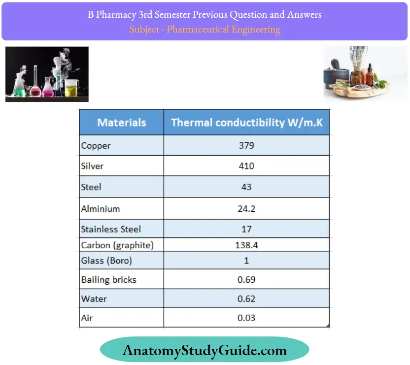
- Thermal conductivities of liquids and gases are very small compared to most of the solids. In other words, the resistance offered by liquids and gases is high as far as the conduction is concerned.
- Metals have high conductivity, although values vary widely.
- Non-metallic solids normally have lower conductivities than metals. Carbon is an exception. Its relatively high conductivity and chemical inertness permit its wide use in heat exchangers.
- For the porous materials of metals, the overall conductivities lie between that of the homogenous solid and the air that permeates the structure. Low resistant values lead to their wide use as heat insulators.
- In the case of steam-jacketed vessels, the kettle (Jon’s surface) must have good conductivity so that the maximum amount of heat passes from the steam to the contents.
- The high thermal conductivity of copper suggests that it is a suitable material for the construction of the kettle.
- At the same time, the metal used for the jacket (outer surface) must have minimum conductivity to prevent loss of heat by conduction and radiation
- The low thermal conductivity of iron suggests that it would be a suitable material for the construction of the jacket. Such materials should be resistant to solvent or chemical action of liquid.
- For the construction of evaporators and tubular heat exchangers thermal conductivity values are helpful.
- Thermal conductivity is very sensitive to changes in chemical composition and temperature and, therefore, the above values cannot be applied to all situations.
Question 9. Explain the theory of drying giving more emphasis on the rate of drying
Answer:
Drying Theory
In a wet solid mass, water may be present as bound water and unbound water.
- Bound water: Moisture is the minimum water (moisture) held by the material that exerts an equilibrium vapor pressure less than the pure water at the same temperature.
- Unbound water: Moisture is the amount of water (moisture) held by the material that exerts an equilibrium vapor pressure equal to that of pure water at the same temperature.
During the drying process, water is easily lost, but the resulting solid is not completely free from water molecules. This is known as air-dry. Easily removable water is the unbound water at the defined environmental conditions.
After the removal of water completely, the material be ‘bone-dry’. Unbound water exists largely in the voids of the solid.
- Thus, in a non-hygroscopic material, all the liquid is unbound water. In a hygroscopic material, the unbound moisture is the liquid in excess of the equilibrium moisture content, corresponding to saturation humidity.
- Substances containing bound water are often called hygroscopic substances.
- The distinction between bound and unbound water depends on the material itself. These are described
- Heat must be transferred to the material to be dried to supply the latent heat required for the vaporization of the ministry.
- Water diffuses through the material to the surface and subsequently evaporates into the air stream. Thus drying involves both heat transfer and mass transfer operations simultaneously.
- Theory can be discussed in three heads namely mechanisms of drying, equilibrium relationships, and rate relationships.
Rate of Theory
- Drying involves both heat transfer and mass transfer processes simultaneously.
- Heat transfer takes place from the heating medium to the solid material.
- The mass transfer involves the transfer of moisture to the surface of the solids and subsequently vapourization from the surface into the surroundings.
Various theories are proposed to explain the movement of moisture:
These are given below.
- Diffusion
- Capillarity theory
- Pressure gradient theory
- Gravity flow theory
- Vaporization and condensation mechanisms
- A few of these theories are explained in the following sections.

Diffusion theory
Diffusion theory assumes that the effect of capillarity, gravitational, and friction forces are too small. In diffusion theory, the rate of flow of water is proportional to a moisture gradient. According to this theory, moisture movement may be as follows.
- Water diffuses through the solid to the surface and subsequently evaporates into the surroundings.
- Evaporation of water occurs at an intermediate zone, much below the solid surface, then vapors diffuse through the solid into the air.
Due to limitations in predicting the drying rate over a range of moisture gradients, this theory is not very applicable. Limitations Diffusivity decreases as the moisture content and temperature decrease while increasing with pressure.
Capillarity theory
Capillarity theory applies to porous granular solids. Porous material contains a network of interconnected pores and channels, which are not circular or straight.
- At the surface, the cross-section of these capillaries forms various sizes of pores. As the drying starts, a meniscus is formed in the capillary and exerts a force. This is the driving force for the movement of water through pores towards the surface.
- The curvature of the meniscus depends on the pore diameter and determines the strength of the capillary force. The capillary force is greater in small pores compared to large pores. Therefore small pores pull more water from the larger pores and thus large pores get emptied first.
- Air enters into the emptied pores and the moisture content is relatively higher near the surface.
- The capillary theory holds good only for free water in the bed. This type of movement of liquid takes place in the granules (pores) as well as in the spaces between the granules (void spaces).
- As the pore diameter is considerably smaller inside a granule than the surrounding granules, the liquid surrounding the granules can be removed initially. Then pore liquid inside granule is vapourized. Diffusion theory applies to hygroscopic material.
Pressure gradient theory
- Pressure gradient theory applies to the drying of solids by the application of radiation (not external heating).
- Radiation is a source for generating internal heat.
- The radiation interacts with the polarized molecules and ions of the material. This field aligns the molecules in order, which are otherwise randomly oriented. When the field is reversed, the molecules return to their original orientation. In this process, it gives up random kinetic energy (or heat) to the inside surface of the solids
itself. - Therefore, the liquid inside the solids is vapourised. As a result, the vapor pressure gradient is developed which is the driving force for the movement of vapor to the surface.
- This type of drying mechanism applies to radiation drying provided such rays penetrate deep inside the solid mass.
Question 10. Derive Bernoculi’s equation stating the assumptions
Answer:
A fluid in motion is subjected to several forces, which result in the variation of the acceleration and the energies in the flow phenomenon.
When the principle of conservation of energy is applied to the flow of fluids, the resulting equation is called Bernoulli’s theorem. pumps generally supply energy for conveying liquids from one point to another. Consider such a pump working under isothermal conditions between points A and B

Bernoulli, ‘s theorem states that in a steady state ideal flow of an incompressible fluid, the total energy per unit mass, which consists of pressure energy, kinetic energy, and datum energy, at any point of the fluid is constant. At point A, one kilogram (unit mass) of liquid is assumed to be entering. At this point, liquid experiences pressure energy, kinetic energy, and potential energy, which are obtained as follows. Since the liquid is flowing through the pipe at a certain pressure, pressure energy in joules may be written as:
Pressure energy PA/gρA …………….. (1)
Where, PA pressure at point A, Pa
g = Acceleration due to gravity, m/s
PA = Density of the liquid,kglm3
Potential energy (datum energy) of the body is defined as the energy possessed by the body by virtue of its position or configuration. Point A is considered at a height of XA meters above the horizontal datum plane. The potential energy for one kilogram of liquid may be written as:
Potential energy: XA …………….. (2)
The kinetic energy of a body is defined as the energy possessed by the body by its motion. Since the liquid is under motion, the velocity of the liquid may be designated as u meter per second at point A. The kinetic energy may be expressed
Kinetic Energy = μ²A/2g ……………. (3)
Expressed as:
The total energy at point A may be summarised by combining equations (1), (2) and (3) as
Total energy pressure energy + potential energy + kinetic energy
 ………………(4)
According to Bernoulli’s theorem, the total energy at point A is constant. Therefore, equation (17) is
 ………………(5)
After the system reaches the steady state, whenever one kilogram of liquid enters at point A, another kilogram of liquid leaves at point B.
Therefore, the energy content of one kilogram of liquid that is being displaced at point B may be written (Bernoulli’s theorem) as
 ………………(6)
Where
XB: Height from the datum to the pipe, m
ug: VelocityatpointB,m/s
PB: Pressure at point B, Pa
ρB: DensityatpointB, kg/m3
If there is no gain or loss of energy, the principle of conservation of energy may be applied to the two points A and B.
Input = Output
Total energy at point A: Total energy at point B

Theoretically, all kinds of energies involved in fluid flow should be accounted for. In the transportation of fluid, the pump has added a certain amount of energy, which can be written as:
Energy added by the pump +wJ ……………. (7)
During the transportation of liquid, some energy is converted to heat due to frictional forces and it is inevitable. The energy loss may be written as:
Loss of energy due to friction in the line FJ ………………(8)
The energy balance between points A and B can be accounted for by including equations (7) and (8) in equation (6). the equation representing such energy may be written as This complete equation representing such energy may be written as:
 ……………..(9)
Equation (9) is called Bernoulli’s equation. Bernoulli’s theorem, although derived over two ends of a system, is applicable between any two points in a system.
Equation (9) is numerically correct. But it is not correct theoretically, since each of the terms in equation (9) is energy tenn and should be measured in the units of joules per unit mass. In practice, these terms are always referred to as heights and are often measured in terms of the height of a column of liquid.
Question 11. How does the film evaporator function? Elaborate the answer with the neat sketch of the climbing film evaporator. List its merits and demerits
Answer:
Climbing Film Evaporator (Rising Film Evaporator)
Climbing film evaporator function Principle:
In climbing film evaporator tubes are heated externally by steam. The preheated feed enters from the bottom and flows up through the heated tubes. The liquid gets heated rapidly due to the enhanced overall coefficient of the preheated feed. The liquid near the wall becomes vapor and forms small bubbles. These tend to fuse to larger bubbles, which travel up in the tubes along with the entrapped slug. The liquid films are blown up from the top of the tubes and the strike entrainment separator (deflector) is kept above. This throws the liquid concentrate down into the lower part from where it is withdrawn.
Climbing film evaporator Construction:
In this evaporator, the heating unit consists of steam-jacketed tubes. Here, the tubes (long and narrow) are held between two plates. An entrainment separator is placed at the top of the vapor head. The evaporator carries a steam inlet, vent outlet, and condensate outlet. The feed inlet is from the bottom of the steam compartment.
Climbing film evaporator Working:
The preheated liquid feed (to be evaporated) is introduced from the bottom of the unit. The height of the liquid column is maintained low, i.e., 0.6 or 1.2 meters above the bottom tube sheet. Steam enters into the spaces outside the tubes through the inlet. Heat is transferred to the liquor through the walls of the tubes. The liquid becomes vaporous and forms smaller bubbles, which tend to fuse to larger bubbles. These are the width of the tubes, thereby the bubbles trap apart the liquid (slug) on its way up in the tubes.
As more vapor is formed, the slug of liquid is blown up in the tubes facilitating the liquid to spread as a film over the walls. This form of liquid continues to vaporize rapidly. Finally, the mixture of liquid concentrate and vapor is ejected at a high velocity from the top of the tubes. The entrainment separator not only prevents entrainment but also acts as a foam breaker. The vapor leaves from the top, while the concentrate is collected from the bottom.

Climbing film evaporator Uses:
- Using a climbing film evaporator, thermolabile can be broken by an entrainment separator.
- Substances such as insulin, liver extracts and vitamins clear liquids, foaming liquids, and corrosive solutions
- Deposit or scales can be removed quickly by increasing the feed rate or reducing the steam rate so that the point is unsaturated for a short time
Climbing film evaporator Advantages/merits
- In a climbing film evaporator, a large area for the transfer is provided by employing long and narrow tubes.
- Since liquid flows at a high velocity, the resistance for heat transfer at the boundary layers is reduced As a result, the heat transfer is enhanced
- The time of contact between the liquor and the heating surface is very hot. The liquid is in the heater for one second, while its residence time is 20 seconds in the evaporator. Hence it is suitable for heat-sensitive materials.
- Unlike short tube evaporators, the tubes are not submerged. So there is no elevation of boiling point due to hydrostatic head
Climbing film evaporator Disadvantages/Demerits:
- Climbing film evaporator is expensive’ construction is in large quantities can be operated. 1′ climbing film evaporator is expensive’ construction is
- It is difficult to clean and maintain
- Large It is not the advised space for very required viscous liquids, salting liquids
- If the feed rate is high, the liquor may be concentrated insufficiently’ If the feed rate is low’ film cannot be maintained’ Dry patches may form on the tube walls’
Question 12. Explain the construction and operational deals of the freeze dryers. Describe the applications in pharmacy
Answer:
Freeze Dryer:
Freeze drying is also known as lyophilization, i.e., the system is made solvent-loving to remove the same
Freeze Dryer Principle:
In freeze drying, water is removed from the frozen state by sublimation, i.e., direct change of water from solid into vapor without conversion to a liquid phase
Solid-liquid-vapour equilibrium phase diagram of water is useful for deciding the experimental conditions. The drying is achieved by subjecting the material to temperature and pressures below the triple point (in practice, below eutectic temperature is essential).
Under these conditions, any heat transferred is used as latent heat, and ice sublimes directly into a vapor state. The water vapor is removed from the system by condensation in a cold trap maintained at a temperature lower than the frozen material.
Freeze Dryer Construction:
It consists of:
- Drying chamber in which trays are loaded.
- Heat supply in the form of radiation source, heating coils.
- Vapor condensing or adsorption system.
- Vacuum pump or steam ejector or both.
The chamber for vacuum drying is generally designed for batch operation. It consists of shelves for keeping the material. The distance between the subliming surface and the condenser must be less than the mean path of molecules. This increases the rate of drying.
The condenser consists of a relatively large surface cooled by solid carbon dioxide slurred with acetone or ethanol. The temperature of the condenser must be much lower than the evaporated surface of the frozen substance. To maintain this condition, the condenser surface is cleaned repeatedly.
Freeze Dryer Working:
The working of a freeze dryer consists of the following steps:
- Preparation and pretreatment
- Prefreezing to solidify water.
- Primary drying (sublimation of ice under vacuum)
- Secondary drying (removal of residual moisture under high vacuum)
- Packing.
These are:
- Preparation and pretreatment: The volume of solution introduced into the container is limited by its capacity.) Satisfactory freeze drying beyond a certain limit of the depth of liquid is not possible. Therefore pretreatment is essential. The solution is pre-concentrated under normal vacuum tray drying. This reduces the actual drying by 8 to 10 times. The final product becomes more porous. Liquid or solid desiccants are also used for this purpose.
- Prefreezing to solidify water: Vials, ampoules, or bottles in which the aqueous solution is packed are frozen on cold shelves (about -50 “C). During this stage, the cabinet is maintained at low temperature and atmospheric pressure. The normal cooling rate is about I to 3 Kelvin per minute so large ice crystals with relatively large holes are formed on sublimation of ice. This is also responsible for giving a porous product.

3. Primary drying (sublimation of ice under vacuum):
In this step, the material to be dried is spread as large a surface as possible for sublimation.
- The temperature and pressure should be below the triple point of water i.e., 0.0098 oC and 0.533 kilopascals, (4.58 mmHg) for the sublimation, when water alone is present.
- When a solution of solid is dried, the depression of the freezing point of water occurs.
- Hence, the temperature must be brought below the eutectic point. The pressure and temperature at which the frozen solid vaporizes without conversion to a liquid is referred to as the eutectic point.
- Depending on the drug substance dissolved in water, the eutectic point is determined.
- The usual range is from -10 “C The condition of 1 to 8 K below the eutectic point is sufficient.
Vacuum is applied to the tune of about 3 mmHg (0.4 kilopascals) on the frozen sample.
- The temperature is linearly increased to about 30 “C in 2 hours.)
- Heat (about 2900 kilojoules per kg) is supplied which transfers as latent heat and ice sublimes directly into the vapor state.
- The heat controls the movements of the ice layer inwards. It has to be controlled in such a manner to get the highest possible water vapor at the ice surface without melting the material. (As soon as vapor molecules are formed, these are removed.
- The overall driving force is the temperature difference (also vapor pressure difference) between evaporating surface and condenser.
- As the drying proceeds, the thickness of the frozen layer decreases and the thickness of partially dried solids increases.)
- The primary drying stage removes easily removable moisture. During this stage, about 98% to 99o/o water is removed.
- Still, traces of moisture are present in the sample.
4. Secondary drying (Removal of residual moisture under high vacuum): During this stage, traces of moisture are removed:
The temperature of the solid is raised to as high as 50 to 60 “C, but the vacuum is lowered below that is used in primary drying (50 mmHg). The rate of drying is very low and it takes about 10 to 20 hours
5. Packing:
Aftervacuum is replaced by inert gas, the bottles and vials are closed.
Freeze Dryer Uses:
Freeze dryers are most commonly used in the production of dosage forms, such as injections, solutions, and suspensions. It is used for drying of several products.
- Blood plasma and its fractionated products.
- Bacterial and viral cultures.
- Human tissue (arteries and corneal tissue).
- Antibiotics and plant extracts.
- Steroids, vitamins, and enzymes.
Several other products such as food items (prawns, mushrooms, meat and poultry products), coffee and tea concentrates, and citrus fruit juices are dried.
Freeze Dryer Advantages:
- The entire operation is carried out well below the freezing point. This offers several advantages.
- Thermolabile materials (heat-sensitive materials) can be dried.
- The product retains its bulk volume. It is porous and uniform. The reconstitution of the material is easy.
- Denaturation does not occur.
- Migration of salts and other solutes does not take place.
- Loss of volatile material is less.
- Moisture levels can be kept as low as possible without decomposition.
- Material can be dried in its final container such as single dose and multiple dose vials.
- The final product can be stored at ambient temperature if well sealed by providing an inert atmosphere.
Freeze Dryer Disadvantages:
- The product is prone to oxidation, due to high porosity and large surface area.
- Therefore, the product should be packed in a vacuum using inert gas or in a container impervious to gases.
- Equipment and running costs are high. It is difficult to adopt the method for solutions containing nonaqueous solvents.
- The period of drying is high (rarely less than 10 hours).
- Time cannot be shortened.
Applications in Pharmacy
- Preparation of bulk drugs: In the preparation of bulk drugs, drying is the final stage of processing. A few examples are:
- Driedaluminiumhydroxide
- Spray dried lactose
- Powdered extracts
- The drying step is essential after certain operations such as crystallization and filtration.
- Preservation of drug products: Drying is necessary to avoid deterioration. A few examples are:
- Crude drugs of animal and vegetable ” chemical decomposition origin
- Blood products, skin, tissue “microbial growth
- Synthetic and semisynthetic drugs “chemical decomposition
- Effervescent tablets”chemical decomposition (aspirin, penicillins)
- Improved characteristics : (Drying produces materials of spherical shape, uniform size, free-flowing, and enhanced solubility.)
Some specific areas of importance are:
- Granules are dried to improve the fluidity and compression characteristics. These are essential for the production of tablets and capsules.
- Viscous and sticky materials are not free-flowing. Drying modifies these characteristics. Examples are male fem extract, malt extract, and oleoresin.
Improved handling:
Removal of moisture makes the material light in weight and reduces the bulk. Thus cost of transportation will be less and storage will be efficient. If moisture is present, size reduction of drugs is difficult. Drying reduces the moisture content.
Question 13. Compare and contrast heat transmission following counter-current and parallel current feed techniques with relevant equations.
Answer:
Counter-current heat flow-temperature gradient: When the hot fluid is passed through one end of the apparatus while cold fluid is passed through the other end, fluids pass and pass each other in opposite directions. This arrangement is known as counter-current or counter-flow
The temperature gradients for the counter-current flow can be concluded that the temperature drop along the length of the apparatus is nearly constant. In other words, the amount of heat transfer per unit area is substantially the same at both ends. The heating surface is nearly constant throughout the apparatus.

In counter-current heat flow, the exit temperature of the hot fluid is considerably less an the exit temperature of the cold fluid. Hence a large proportion of the heat content of the hot fluid can be extracted for a given entrance temperature of the cold fluid. If Δt1 = Δt2 temperature (Δt) can be taken as an arithmetic average.
Δtave = Δt1 +Δt2 / 2 ……………….. (1)
The heat transfer equation for counter-current heat flow can be written as:
q = UA.Δtave
Consider a case, where steam is transferring its heat to a colder body. Let the pressure difference in steam be constant.
![]()
Initially steam cools down to the condensing temperature as indicated by AB in. Then condensation occurs at a constant temperature.
(section BC), and may further be allowed to cool (section CD). Here large errors would be introduced, if AF and DE are taken for Dt and D12, respectively. Separate heat transfer calculations must be done for the three sections in Figure 5-9 and then are added.
Parallel heat flow-Variation in temperature:
Heat transfer across a metal surface from a hot fluid to a cold fluid depends on the temperature gradient (M) Generally, it is assumed to be constant for all parts of the heating surface. When the hot fluid and the cold fluid enter the apparatus from the same end, the flow is parallel to each other. This arrangement is known as parallel flow. Consider a heat interchanger. The temperature of the hot fluid inside a pipe decreases from T1 to T2 by transferring heat to a cold fluid outside the pipe. As a result, the cold fluid temperature is increased from t1 to t2.

The temperature drop at the left end is much greater than at the right end. It means that heat transfer is faster on the left side than on the right side. These changes, as occurring in a small section of the pipe, can be considered for the whole length of the pipe.
Mathematically, heat transfer in parallel flow of liquids can be written as:
dq = U.A.Δt ……………….. (3)
The equation is based on two assumptions,
- The overall coefficient (U) is considered constant throughout the equipment,
- The specific heat of each fluid is considered constant. Integrating equation(31) gives:
Δt1 -Δt2
q = Ual In Δt1 / Δt2 ……………. (4)
Where L = Length of pipe. m
a = Area of the pipe, m²
Δtm = Δt1 – Δt2 / Δt1 / Δt2 …………. (5)
Thus logarithmic mean temperature difference (Atm) is used. The total heating surface (A) is equal to al. Heat transfer equation in parallel flow heat ex-changer is:
q = UAΔt1 ………………… (6)
The logarithmic mean temperature difference is used to account for varying temperature drops in parallel flow. If the temperature drop is nearly equal (A1 A2), then arithmetic average temperature (AFM) can be used, which is a general expression for heat transfer.
In parallel heat flow, the heating obtained per unit surface area is much less effective at the fluid exit point compared to it at the point of entrance of the apparatus
Question 14. Write the theory of solid-solid mixing. Explain the principle, construction, and working of the planetary mixer.
Answer:
Mechanisms Of Mixing In Solids:
Segregation of particles occurs due to several reasons
Mixing can prevent it. The principal mechanisms in solid-solid mixing are:
- Convective Mixing: It is achieved by the inversion of the powder bed using blades or paddles or screw elements. A large mass of material moves from one part to another, Congestive mixing is referred to as macromiting.
- Shear Mixing In this type, the forces of attraction are broken down so that each particle moves on its own between regions of different compositions and parallel to their surfaces. In a particulate mass, the forces of attraction are predominating, which makes the layers slip over one another. Such types of attraction forces are predominant among the same type of particles. Shear forces reduce these attractions and reduce the scale of segregation.
- Diffusive Mixing: It involves the random motion of particles within the powder bed. Thereby particles change their positions relative to one another. Diffusive mixing occurs at the interfaces of dissimilar regions. Diffusion is sometimes referred to as micromixing.
The motion of particles to achieve random distribution assumes that no other factor influences the distribution. This is rarely the case. Instead, several properties of the powders influence the approach to randomness. Flow characteristics of powders largely determine the ease with which the primary particles can be mixed.
Planetary Mixer
Planetary Mixer Principle:
In a planetary mixer, the blade tears the mass apart and shear is applied between a moving blade and a stationary wall. The mix ng arm moves in two ways, around its axis and the central axis, so that it reaches every spot of the vessel. The plates in the blade are sloped so that the powder makes an upward movement. Therefore, turn bling (convective) motion is also obtained.
Planetary Mixer Construction
It consists of a vertical cylindrical shell, which can be removed either by lowering it beneath the blade or raising the blade above the bowl. The mixing blade is mounted from the top of the bowl. The mixing shaft is driven by a planetary gear train. It rotates around the ring gear, which further rotates around the mixer blade. It is normally built with a variable-speed drive

Planetary Mixer Working:
In the planetary mixer, the agitator has a planetary motion. It rotates on its own and around the central axis so that it reaches all parts of the vessel. The beater is shaped to pass with close clearance over the side and bottom of the mixing bowl.
Therefore, there are no dead spaces in the mixing bowl. The blade tears the mass apart and shear is applied between the moving blade and the stationary wall. The plates in the blade are sloped so that the powder makes an upward movement. Therefore, tumbling (convective) motion is also obtained.
Since it is variable speed driven, initially the blade moves slowly for premixing and finally at increased speed for active mixing. Thus high shear can be applied for mixing. Emptying the bowl may be done by hand (scooping) or by dumping mechanism.
Planetary Mixer Uses:
- Planetary mixer produces precise blends in addition to breaking down agglomerates rapidly.
- Low speeds are used for dry blending and faster speeds are for the kneading action required in wet granulation.
- Steam-jacketed bowls are used in the manufacture of sustained-release products and ointments.
Planetary Mixer Advantages:
- The speed of the rotation can be varied at will, so it is advantageous over sigma blade or ribbon-type blenders.
- This is more useful for the wet granulation process.
- There are no packing glands in contact with the product.
Planetary Mixer Disadvantages :
- Mechanical heat is built up within the powder mix.
- It requires high power.
- It has a limited size and is useful for batch work only.
Question 15. Explain the construction, and working of different manometers.
Answer:
Differential manometers:
The differential manometer is a manometer that measures the difference of pressures between any two points in a pipe or vessel containing fluid. Differential manometers find occasional applications. This manometer is suitable for the measurement of small pressure differences. It is a sensitive device and useful for measuring even small gas pressures (heads).
Differential manometers Construction:
The differential manometer is also known as a two-fluid U-tube manometer. It contains two immiscible liquids A and B having nearly the same densities. The U tube consists of enlarged chambers on both limbs. Hence, the meniscus of the liquid in these enlarged chambers does not change appreciably with changes in the reading R.
Using the principle of simple manometers, the pressure difference (ΔP pascals) can be written as:
ΔP = P – P2 = R(PC – PA)g ……………………………..(1)
Equation (1) indicates that the smaller the difference
(PC – PA), the larger will be reading on the manometer
(R meters) for a given value of AP.
Differential manometers Applications:
- Micromanometers based on the liquid column principle are available commercially.
- They measure the reading with extreme precision and sensitivity. These are free from errors due to capillarity and require no calibration, apart from checking the micrometer scale.

Question 16. Explain the construction and working of the bag filter.
Answer:
Bag Filter Principle:
In a bag filter, size separation of fines (or dust) from the milled powder is achieved in two steps. In the first step, the milled powder is passed through a bag filter (cloth) by applying the suction on the opposite side of the feed entry. This facilitates the separation. In the next step, pressure is applied to shake the bags so that powder adhering to the bag falls off, which is collected from the conical base.
Bag Filter Construction:
It consists of several bags made of cotton or wool fabric. These are suspended in a sheet metal container. A hopper is arranged at the bottom of the filter to receive the feed. At the top of the metal container, a provision is made for the exhaust Adjacent to this, a bell crank lever arrangement is made to bring the filters to normal atmospheric conditions.
Bag Filter Working:
The working of the bag filter consists of two steps. In the first step, the feed is separated from air by passing it through the cloth bags. In the subsequent step, the bags are shaken to collect the fines that are adhered to the bags. These two steps follow in succession and are controlled at different intervals with the help of a bell crank lever arrangement

Bell crank lever arrangement:
In this mechanism, a shaft with a cam is allowed to rotate at a low speed. During rotation, the cam can either press the bell crank lever or does not come into contact. Depending on this mechanism, the damper changes its position.
The damper is a useful mechanism, which allows the two steps to occur as shown below.
- Filtering period: The exhaust fan positioned at the top keeps the bags under less pressure than atmospheric pressure. The gas containing fine particles (or dust) enters the hopper and passes up. The gas feed passes through the fabric of the bag. During this process, the fines (or dust) are retained in the bags, while the gas reaches the top of the casing. Because of air, the bag remains taut during filtering operation.
- Shaking period: Since the vacuum is cut off in the chamber, air from outside enters the casing and passes through the bags. This results in violent shaking of the bags so that the dust and fine particles are displaced from the bags and fall into the conical base. It is then removed at intervals. Such devices are entirely automatic in their action and can be designed to affect very large filtering surfaces per unit of floor space.

Bag Filter Uses:
- Bag filters are used along with other size separation equipment, for example, a cyclone separator.
- Bag filters are used to remove the fines from cyclone discharge. The bag filter is connected to the discharge end of the fluidized energy mill.
Bag Filter Advantages
- A bag filter is extremely useful for removing fines, which cannot be separated by other methods.
- These can be used even to remove dust. The ordinary household vacuum cleaner is a simple bag filter. Disadvantage: Bag filter is not size separation equipment as such
Question 17. Describe the principle with the help of a labeled diagram of a fluidized bed dryer.
Answer:
Fluidized Bed Dryer (FBD) Principle:
In a fluidized bed dryer, hot air (gas) is passed at high pressure through a perforated bottom of the container containing granules to be dried. The granules are lifted from the bottom and suspended in the stream of air. This condition is called a fluidized state. The hot gas surrounds every granule to completely dry them. Thus, materials or granules are uniformly dried.
Fluidized Bed Dryer Construction:
Two types of bed dryers are available, vertical fluid bed dryer and horizontal fluid bed dryer. The dryer is made up of stainless steel or plastic. A detachable bowl is placed at the bottom of the dryer, which is used for charging and discharging. The bowl has a perforated bottom with a wire mesh support for placing materials to be dried. A fan is mounted in the upper part for circulating hot air.
Fresh air inlet, prefilter, and heat exchanger are connected serially to heat the air to the required temperatures. The temperature of hot air and exit air are monitored. Bag filters are placed above the drying bowl for the recovery of fines.

Fluidized Bed Dryer Working:
The wet granules to be dried are placed in the detachable bowl. The bowl is pushed into the dryer. Fresh air is allowed to pass through a pre-filter, which subsequently gets heated by passing through a heat exchanger. The hot air flows through the bottom of the bowl. Simultaneously fan is allowed to rotate. The air velocity is gradually increased.
When the velocity of the air is greater than the settling velocity of granules, the granules remain partially suspended in the gas stream. After some time, a point of pressure is reached at which frictional drag on the particles is equal to the force of gravity.
- The granules rise in the container because of high-velocity gas (1.5 to 7.5 meters per minute) and later fall back in a random boiling motion. This condition is said to be a fluidized state.
- The gas surrounds every granule to completely dry them.
- The air leaves the dryer by passing through the bag filter. The entrained particles remain adhered to the inside surface of the bags. Periodically the bags are shaken to remove the entrained particles.
- Intense mixing between granules and hot gas provides uniform conditions of temperature, composition, and particle size distribution.
- Drying is achieved at a constant rate and the falling rate period is very short. Any attempt to increase the air velocity may result in entrainment.
- The residence time for drying is about 40 minutes. The material is left for some time in the dryer to reach ambient temperature. The bowl is taken out for discharging. The end product is free-flowing.
Fluidized Bed Dryer Uses:
A fluidized bed dryer is popularly used for drying granules in the production of tablets. A fluidized bed dryer can be used for three operations such as mixing, granulation, and drying. It is modified for the coating of granules.
Fluidized Bed Dryer Advantages:
- A fluidized bed dryer requires less time to complete drying, i.e., 20 to 40 minutes compared to 24 hours of tray dryer. Handling time is also short. It is 15 times faster than the tray dryer.
- It is available in different sizes with a drying capacity ranging from 5 to 200 kg per hour.
- The drying containers are mobile, making handling simple and reducing labor costs.
- The thermal efficiency is 2 to 6 times that tray dryer.
- It is also used for mixing the ingredients and its mixing efficiency is also high.
- Hot spots are not observed in the dryer, because of its excellent mixing and drying capacities.
- Higher drying temperatures can be used that are not possible in tray dryers and truck dryers.
- It facilitates the drying of thermolabile substances since the contact time for drying is short.
- It can be used either as batch type or continuous type.
- It has a high output from a small floor space.
- The free movement of individual particles eliminates the risk of soluble material migrating as may occur in static beds
Fluidized Bed Dryer Disadvantages :
- Many organic powders develop electrostatic charges during drying. To avoid this, efficient electrical earthing of the dryer is essential.
- The turbulence of the fluidized state of granules may cause attrition of some materials resulting in the production offices. But using a suitable binding agent this problem can be solved.
- Fine particles may become entrained and must be collected by bag filters
Question 18. Explain the process of washing of cake in a filter press.
Answer:
Plate and Frame Filter Press Principle:
The mechanism is surface filtration. The slurry enters the frame by pressure and flows through the filter medium. The filtrate is collected on the plates and sent to the outlet. A number of frames and plates are used so that surface area increases and consequently large volumes of slurry can be processed simultaneously with or without washing.
Plate and Frame Filter Press Construction:
The filter press is made of two types of units, plates and frames. These are usually made of aluminum alloy. Sometimes, these are also lacquered for protection against corrosive chemicals and made suitable for steam sterilization.
The frame contains an open space inside wherein the slurry reservoir is maintained for filtration and an inlet to receive the slurry.
- The plate has a studded or grooved surface to support the filter cloth and an outlet. The filter medium (usually cloth) is interposed between plate and frame.)
- Frames of different thicknesses are available. It is selected based on the thickness of the cake formed during filtration. The optimum thickness of the frame should be chosen. (Plate, filter medium, frame, filter medium, and plate are arranged in the sequence and clamped to a supporting structure.
- It is normally described by dots as (1.2.1.2.1 so on.
- Several plates and frames are employed so that the filtration area is as large as necessary. In other words, several filtration units are operated in parallel
- Channels for the slurry inlet and filtrate outlet can be arranged by fitting eyes to the plates and frames, these join together to form a channel. In some types, only one inlet channel is formed, while each plate has individual outlets controlled by valves.
Plate and Frame Filter Press Working:
The working of the frame and plate process can be described in two steps, namely filtration and washing of the cake (if desirable).
Filtration operation:
The working of plate and frame press is shown in Figure 8-8. Slurry enters the frame (marked by 2 dots) from the feed channel and passes through the filter medium onto the surface of the plate (marked by 1 dot). The solids form a filter cake and remain in the frame. The thickness of the cake is half of the frame thickness because, on each side of the frame, filtration occurs. Thus, two filter cakes are formed, which meet eventually in the center of the frame. In general, there will be an optimum thickness of filter cake for any slurry, depending on the solid content in the slurry and the resistance of the filter cake.

The filtrate drains between the projections on the surface of the plate and escapes from the outlet. As filtration proceeds, the resistance of the cake increases and the filtration rate decreases. At a certain point, it is preferable to stop the process rather than continue at very low flow rates. The press is emptied and the cycle is restarted

Washing operation:
If it is necessary to wash the filter cake, the ordinary plate and frame press is unsatisfactory. Two cakes are built up in the frame meeting eventually in the middle. This means that flow is brought virtually to a standstill.
Hence, water washing using the same channels of the filtrate is very inefficient, if not impossible. A modification of the plate and frame press is used. These wash plates are identified by three dots. In half the wash plate, there is a connection from the wash water channel to the surface of the plate,

The sequence of arrangement of plates and frames can be represented by dots as 1:2:3:1:1:3:2:1:2:3:2:1 and so on (between and 1, 2.3.2 must be arranged). Such an arrangement is for the operations of irrigation and water washing, respectively.
The steps are as follows:
- Filtration proceeds in the ordinary way until the frames are filled with cake.
- To wash the filter cake, the outlets of the washing plates (three dots) are closed.
- Wash water is pumped into the washing channel. The water enters through the inlets onto the surface of the washing (three dots) plates.
- Water passes through the filter cloth and enters the frame (two dots) which through the filter cloth and enters the plate (one dot) down the surface.
- Finally, washed water escapes through the outlet of that plate.
Thus with the help of special washing plates, the wash water can flow over the entire surface of the washing (three dots) plate, so that the flow resistance of the cake is equal to all points. Hence, the entire cake is washed with equal efficiency.
It should be noted that water washing is efficient only if the frames are full of filter cake. If the solids do not fill the frame, the wash water causes the cake to break (on the washing plate side of the frame), then washing will be less effective.
Hence, it is essential to allow the frames to become filled with the cake. This helps not only in emptying the frames but also helps in washing the cake correctly.


Special provisions:
Any possible contamination can be observed by passing the filtrate through a glass tube or sight gas from the outlet on each plate. This permits the inspection of the quality of the filtrate. The filtrate goes through the control valve to an outlet channel. The filtration process from each plate can be seen. In the event of a broken cloth, the faulty plate can be isolated and filtration can be continued with one plate less.
Plate and Frame Filter Press Uses:
Filter sheets composed of asbestos and cellulose are capable of retaining bacteria so that sterile filtrate can be obtained, provided that the whole filter press and filter medium have been previously sterilized. Usually, steam is passed through the assembled unit for sterilization.
Examples include collection of precipitated antitoxin, removal of precipitated proteins from insulin liquors, and removal of cell broth from the fermentation medium. Heating/cooling coils are incorporated in the press to make it suitable for the filtration of viscous liquids.
Plate and Frame Filter Press Advantages:
- Construction of filter press is very simple and a variety of materials can be used.
- Cast iron for handling common substances. Bronze for smaller units. Stainless steel is used thereby contamination can be avoided.
- Hard rubber or plastics where metal must be avoided.
- Wood for lightness though it must be kept wet.
- It provides a large filtering area in a relatively small floor space. It is versatile, the capacity being variable according to the thickness of frames and the number used.
- Surface area can be increased by employing chambers up to 60.
- The sturdy construction permits the use of considerable pressure difference. About 2000 kilopascals can be normally used.
- Efficient washing of the cake is possible.
- Operation and maintenance are straightforward because there are no moving parts, and filter cloths are easily renewable.
- Since all joints are external, a plate can be disconnected if any leaks are visible. Thus contamination of the filtrate can be avoided.
- It produces dry cake in the form of a slab.
Plate and Frame Filter Press Disadvantages:
- It is a batch filter, so there is a good deal of ‘down¬ time’, which is non-productive.
- The filter press is an expensive filter. The emptying time, the labor involved, and the wear and tear of the cloth result in high costs..
- Operation is critical, as the frames should be full, otherwise washing is inefficient and the cake is difficult to remove.
- The filter press is used for slurries containing less than 5% solids. So high costs make it imperative that this filter press is used for expensive materials.
- Examples include the collection of appreciated antitoxin and removal of precipitated proteins from ins in liquors
Question 19. List five pharmaceutical; applications of centrifugal separations.
Answer:
Process of Centrifugation:
The centrifuge consists of essentially a container in which a mixture of solid and liquid or two liquids is placed and rotated at high speeds. The mixture is separated into its constituent parts by the action of centrifugal force on their densities. A solid or liquid of higher specific gravity is thrown outward with greater force. Therefore, it is retained at the bottom of the container leaving a clear supernatant layer of pure liquid. The speed of the centrifuge is commonly expressed in terms of the number of revolutions per minute of the rotor.
Centrifugal separations Applications:
1. Production of bulk drugs:
The centrifugation technique is used to separate crystalline drugs such as aspirin from the mother liquor. Free-flowing product results due to the removal of traces of mother liquor and avoidance of effervescence
2. Production of biological products:
Most of the proteinaceous drugs and macromolecules are present as colloidal dispersion in water. By normal methods, it is difficult to produce them on a large scale. Centrifu gal methods are used for the separation of these constituents from water. Insulin can be obtained in pure form by selectively precipitating other fractions of proteins and subsequently separating them by ultracentrifugation. Centrifugation is employed for separating the blood cells from the blood.
3. Biopharmaceutical analysis of drugs:
Drugs present in the blood, tissue fluids, and urine are normally present in the form of colloidal dispersions. Centrifugation is used for separating the drugs. This method is essential for the evaluation of pharmacokinetic parameters and bioequivalence studies.
4. Evaluation of suspensions and emulsions:
The Centrifugation method is used as a rapid empirical test parameter for the evaluation of suspensions and emulsions. Normally, creaming is slow process in emulsions. This process can be hastened by inducing stress conditions (using a centrifuge). A stable emulsion should not show any signs of separation even after centrifuging at 2000- 3000 revolutions per minute at room temperature
5. Determination of molecular weight of colloids:
Determination of the molecular weight of a polymer is not possible by usual methods. Ultra centrifugation methods are used for the determination of the molecular weight of serum albumin, insulin, and methylcellulose.
Centrifugation (ultra-cen centrifugation) is also used for ascertaining the degree of homogeneity of the sample. For example, insulin is a monodisperse protein composed of two polypeptide chains, whereas gelatin is found to be a polydisperse protein with fractions of molecular weight 10,000 to 1,00,000
Question 20. Describe the construction and working of the screw conveyor.
Answer:
Screw conveyors:
Screw conveyors were used as low-height lift pumps to irrigate the lands. It comprises an inclined rotating casing with an internal helical screw thread, called flight. When such a casing is rotated with its lower end submerged in water, the water entrained in the pockets, formed by the pitches, is raised. The performance of such screws is limited by the angle of inclination of the casing.
A modified version of such screws has been tried with a rotating shaft having helical screw thread moving inside a stationary casing for lifting fluids like sewage sludge. However, due to various limitations, the process achieved limited success in the field of transportation of liquid. However, when a rotating screw shaft in a stationary casing is used to convey solids, it has commendable success.
Screw conveyors Construction and working:
A screw conveyor consists essentially of a shaft-mounted screw rotating in a trough and a drive unit for running the shaft. The material is moved forward along the axis of the trough by the thrust of screw thread or flight. The trough is usually of the U-shape.
A helical blade is attached to a drive shaft which is coupled to a drive unit. The shaft is supported by two end bearings and intermediate bearings. The U-shaped trough has a cover plate with an opening for loading the conveyor. A discharge opening is provided at the bottom of the trough. The loading and discharging points can be located anywhere along the trough. More than one feed hopper and discharge hopper may be fitted according to the necessity.
Evaluating the demand load based on the material properties and choosing the right screw conveyors (trough, pipe, flights, shafts, bearings, and motor-driven controls) is critical for an accurate screw conveyor design.
- Ascrew conveyors that have been correctly built and constructed should be able to meet the demands of any demanding application for many years.
- Screw conveyors, like many other kinds of rotating equipment, need precise alignment to operate well and for an extended period.
- The most straightforward method of checking alignment is to use a string.
- Fasten the string line to one end of the screw conveyor at the trough-end centerline, and then draw the string line tight to the other end of the screw conveyor to complete the installation.
- The misalignment of the trough portions will be seen as a result of this.
- The screw conveyor’s whole length must be aligned, both horizontally and vertically, to ensure proper operation.
- Every five feet, you should use a measuring tape to check for misalignment in both the horizontal and vertical directions.
- In the horizontal direction, taking a horizontal measurement from the string line to the edge of the trough reveals that the screw conveyor is out of alignment in that direction.
In a similar vein, measuring the distance between the string line and the bottom of the trough flange yields vertical misalignment.
- Each horizontal and vertical measurement should be documented. The relative discrepancies in the measurements show how far each trough section has to be moved to ensure appropriate alignment with the others.
- Screw conveyors that are longer than, say, 25 feet may cause a typical misalignment issue with numerous hanger-bearing positions, which is a prevalent difficulty in the manufacturing industry.
- Because the screw is locked at the bearing sites, misalignment results in the application of bending loads at the hanger positions, which are promptly reversed with each rotation
- Alignment results in the application of bending loads at the bearing locations.
- When these cyclical pressures are applied, the result is comparable to the effect of repeatedly twisting a paperclip until it snaps in half.
- Cyclical loading identifies the screw’s weakest zone, which is often located near the hanger bearings and in the screw bushing region, and places it under tension.

The principle of material movement along the trough is similar to the sliding motion of a nut along a rotating screw when the nut is not allowed to rotate. The weight of the material and the friction of the material against the wall prevent the load from rotating with the screw
Question 21. Differentiate between ideal and actual screens.
Answer:
An ideal screen would sharply separate the feed mix in such a way that the smallest particle in overflow would be just larger than the largest particle in underflow Ideal separation defines a cut diameter Dc, the point of separation between oversize and undersize fractions, and is equal to the aperture size of the screen. Actual screens do not give a perfect separation about the cutting diameter. The undersize can contain a certain amount of material coarser than Dp and the oversize can contain a certain amount of material that is smaller than D in the cut diameter.
Question 22. Explain the term evaporator capacity.
Answer:
Evaporator Capacity:
The total amount of heat required can be obtained by considering a simple diagram of the evaporator as shown below. Feed and steam are admitted into the evaporator. By consuming heat, the feed undergoes evaporation to form a vapor, which will be allowed to escape. The concentrated product will be collected at its bottom. Simultaneously steam loses its heat energy and undergoes condensation, the condensate of which will be removed
Let F kg be the feed per hour to the evaporator, whose solid content is XF (weight fraction) and enthalpy is hF kg

Let L kg be the product collected per hour from an evaporator, whose solute composition is XL (weight fraction) and whose enthalpy is hL J/kg. Let V kg be the vapor liberated per hour from an evaporator, whose solute composition is y (weight fraction) and enthalpy is hL J/kg. In most evaporators, the vapor is pure water as there is no entrainment and therefore y is zero.
Question 23. Distinguish between evaporation and distillation.
Answer:
Distinguish between evaporation and distillation:
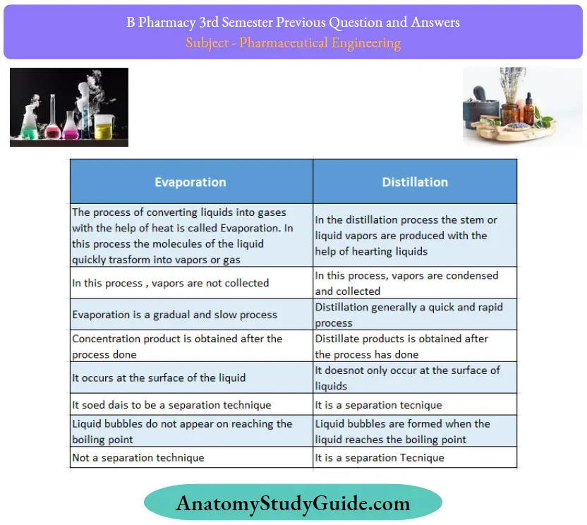
Question 24. Classify dryers by giving suitable examples
Answer:
Classification Of Dryers:
The classification based on the method of solids handling is more suitable when special attention is given to the nature of the material to be dried. Dryers are classified as follows:
1. Static Bed Dryer:
Systems in which there is no relative movement among the solid particles being dried, although there may be a bulk motion of the entire drying mass.
Example: Tray dryer and freeze dryer
2. Moving Bed Dryer:
Systems in which the drying particles are partially separated so that they flow over each other
Example: Drum drier.
3. Fluidized Bed Dryer:
Systems in which the solid particles are partially suspended in an upward-moving heated gas system
Example: Fluidised bed dryer
4. Pneumatic Dryer:
Systems in which drying particles are entrained and conveyed at a high-velocity gas stream
Example: Spray dryer.
Give suitable dryers used for:
- Obtaining free-flowing solids
- Sticky pastes.
1. Obtaining free-flowing solids:
Example: Rotary Dryer (Internal Drum); Vacuum Dryer; Tubular Vacuum Dryer.
2. Sticky pastes.
Example: Tray dryers.
Question 25. Explain the principle behind centrifugation.
Answer:
Behind the centrifugation Principle:
Centrifugation is a unit operation employed for separating the constituents present in a dispersion with the aid of centrifugal force. Centrifugal force provides the driving force for the separation. It replaces gravitation forces operating during the sedimentation. Centrifugation is particularly useful when separation by ordinary filtration is difficult, for example, when separating highly viscous mixtures and colloidal dispersions (particle size less than 5 mm), in which the difference in the densities is less.
In short, centrifugation provides a convenient method of separating either two immiscible liquids or a solid from a liquid. The equipment used for the separation is known as centrifuges. The centrifuge consists of essentially a container in which a mixture of solid and liquid or two liquids is placed and rotated at high speeds.
The mixture is separated into its constituent parts by the action of centrifugal force on their densities. A solid or liquid of higher specific gravity is thrown outward with greater force. Therefore, it is retained at the bottom of the container leaving a clear supernatant layer of pure liquid. The speed of a centrifuge is commonly expressed in terms of the number of revolutions per minute of the rotor.
Question 26. Enumerate the types of glass
Answer:

Question 27. List the advantages and disadvantages of plastic as packaging material
Answer:
Plastic as packaging material Advantages :
- Plastic is light in weight.
- They can be easily molded and have excellent finishing.
- They possess very good strength and toughness.
- They possess good shock absorption capacity.
- Plastic is corrosion-resistant and chemically inert.
- They have a low thermal expansion coefficient and possess good thermal and electrical insulating properties.
- Plastic is very water resistant and possesses good adhesiveness.
- Plastic is strong, good, and cheap to produce.
- Plastic is a recycling process and it does not decompose.
- Plastic bottles can be reused and restored over again and again.
- Plastic is one of the unbreakable
- Plastic is odorless.
- Plastic is used for building, construction, electronics, packaging (gladwrap), and transportation industries.
- Used to make Water bottles, pens, plastic bags, cups, etc.
- Plastic is Very cheap to make Durability, Strength,
- Chemical resistance.
- plastic is used to produce other products.
- Used to reduce soil and wind erosion.
Plastic as packaging material Disadvantages:
- Plastic is a nonrenewable resource.
- Plastic is soft.
- Causes cancer
- Plastics are embrittlement at low temperatures.
- Plastics are deformation under load.
- Plastics are low heat resistant and have poor ductility.
- Plastics are combustible.
- Produces toxic fumes when it is burnt
- It is a recycling process, but it is very costly
Question 28. Explain measures to check the problems of corrosion.
Answer:
1. Selection of Proper Material:
Corrosion should not be permitted in fine mesh wire screens, orifices, and other items in which dimensions are critical and changes are not permitted.
- In many cases, non-metallic materials will be useful and attractive from the point of view of economics and performance.
- These should be considered if their strength, temperature, and design specifications are satisfactory.
- The corrosion characteristics of chemicals and limitations of construction materials must be considered from the literature before selecting equipment. In addition, processing conditions to which the material is exposed should also be considered.
- For this purpose, relevant literature should be consulted.
- Permissible corrosion rates are important factors and differ with equipment.
- Appreciable corrosion can be permitted for tanks and lines if anticipated and allowed for thickness in its design.
2. Proper Design of Equipment:
In the design of equipment, a number of fittings such as baffles, stiffeners, drain nozzles, location of valves and pumps should be considered. Corrosion can be minimized if the equipment design facilitates:
- Elimination of crevices.
- Complete drainage of liquids.
- Ease of cleaning.
- Ease of inspection and maintenance.
On the basis of these general principles, some poor and good engineering designs are given below. A direct contact between two metals should be avoided, if they are separated widely in the electrochemical series. Otherwise, they should be insulated. Equipment should be supported in such a way that it will not rest in pools of liquid or on damp insulating material.
3. Coatings and Linings:
Nonmetallic coatings and linings can be applied on steel and other materials of construction in order to combat corrosion. Appropriate methods such as electroplating, cladding, and organic coatings should be considered.) The thickness of the linings is important (100 mils). Effective linings can be obtained by bonding directly to substrate metal building multiple layers or lamination.

Organic coatings are used as linings in equipment such as tanks, piping pumping lines, and shipping containers.
Some examples of the timings are:
Carbon brick, Glass coated, Plastic, ceramic, elastic, Organic A thin non-reinforced paint-like coating of less than 0.75 mm thickness should not be used in services for which full protection is required from corrosion.
Some examples of linings and uses are:
- Tin-coated steel (tin plate): Food containers
- Lead (Pb) coating (Terme plate): Roofings
- Alluminium (AI) content: Steel high temp conditions
- Zine (Zn) coated steel: Many atmospheric conditions.
The cladding (ie, mechanical bonding) of steel with an alloy is another approach to this problem.
For instance, special glasses can be bonded to steel so that the liner is 1.5 mm thick which is impervious. Equipment and pipings are lined in this manner and routinely used in severely corrosive acid services. The only limitation of this method is the service behavior of the protective coatings.
4. Altering Environment:
Corrosion can be combated or reduced by employing the following environmental conditions.
- Removing air from boiler feed water prevents the influence of water on steel.
- Reducing aeration prevents the formation of passive oxide film in stainless steel alloys by acidic media.
- Pumping of inert gas into solutions prevents the contact of air or oxygen as in the case of nickel-based alloys.
- Reducing the temperature.
- Eliminating the moisture.
- Reducing the velocity or turbulence.
- Shortening the time of exposure.
The addition of acid media should be done as a last step so that maximum dilution can be obtained.
5. Cathodic Protection:
The cathodic protection is based on the galvanic action between the metal(s) of the plant (cathode) and the anode suspended in the solution. The metal to be protected is made a cathode, ie, electrons are supplied, thereby dissolution of metal is suppressed.
This can be achieved by two methods.
- Sacrificial anode method
- Impressed emf method
Sacrificial anode
In this method in this method, anodes are kept in electrical contact with the metal to be protected (cathode). The anodes are sacrificed, since it goes into solution.
For example:
For the protection of iron and steel tanks, metals such as zinc, aluminum, magnesium, and their alloys are used as sacrificial anodes. These are used in a limited pH range when a high solution rate is acceptable since these are amphoteric. Anode metal is selected from the electrochemical series amongst the metals present above the tank metal. The anode should not be poisonous and not detrimental to the product.

Impressed emf method:
This is also known as the applied current system, i.e., the external voltage is impressed between the tank and electrodes. The negative terminal of the power supply is connected to the material to be protected. Therefore, the natural galvanic effect is avoided and the anode is maintained positive.
The term ‘impressed emf’ (or current) means the current which is greater than the corrosion current. When such an impressed current is applied in the opposite direction, the corrosion effect is nullified. Under such conditions, the anode is converted to a cathode in the corroding metal. Since anode is not consumed, any conducting material, metal, or noncorrodable alloys can be used.
For example:
In the case of sulphuric acid and deionized water, graphite and high silicon steel are impressed. The anodes can be buried in the ground or suspended in the aqueous solution of electrolyte
.
6. Anodic Protection:
In the method, a predetermined potential is applied to the metal specimen, and the corresponding current changes are observed. During the initial stage, the current increases indicating the dissolution (corrosion) of the metal.
- When the current reaches a critical point, passivization occurs, i.e., the oxide layer sets in a suitable oxidizing environment.
- The potential at the critical point is called passivating potential. Above this passivating potential, the current flow decreases to a very small value called passivating current.
- The passivating current is defined as the minimum protective current density required to maintain passivization.
- Passivity is a phenomenon in which a metal or alloy exhibits much higher corrosion resistance than expected from its position in the galvanic cell.
- At this stage, an increase in potential will not corrode the metal since the latter is in a highly passive state.
For example:
In the case of stainless steel, titanium becomes easily passive and cannot offer cathodic protection. In such cases, the corrosion rate may be slowed down by the use of anodic current’
Question 29. Write Rittinger’s equation and explain the terms.
Answer:
Rittinger’s theory:
According to this theory energy E required for size reduction of unit mass is directly proportional to the new surface area produced.
E= KR (Sn-Si)……………………………….(1)
Where
Si = initial surface area
Sn = new specific surface area
KR = Rittinger’s constant.
E = amount of energy.
The energy required for size reduction is proportional to the change in surface area of the pieces of food
E = K = (1/d1 -1/d2)
E(J.kg) the energy required per mass of feed (W/(kg/s))
KR: Rittinger’s constant,
d1 (m): The average initial size of pieces.
d2(m): The average size of ground particles
Question 30. Give the graphical representation of the rate of drying curve mentioning different stages of drying.
Answer:
Rate of drying:
Drying is defined as the removal of small amounts of water or other liquid from a material by the application of heat.
Drying is a downstream operation commonly utilized in the last stage of the process and thus has considerable importance. Drying means complete dryness or a condition known as air-dry. The liquid can be organic such as chloroform, ethanol, and isopropanol. Drying is also applied for the removal of small quantities of water or liquid from gases, as in the case of drying of gases
Drying rate = Weight of water in the sample / Time(h) x Weight of the dry solid(kg)
The drying rate is plotted against the midpoints of the time period. Similarly, midpoints of the moisture content values can be plotted.
From the data obtained by the above experiment, a graph is plotted by taking FMC on the x-axis and drying rate on the y-axis. The curve so obtained is called the drying rate curve. It represents different changes during drying as explained below.

Leave a Reply