Extraoral Radiographic Techniques Essay Questions
Question 1. Discuss panoramic radiography in detail.
(or)
Explain in detail principles, technique, indications, advantages, and disadvantages of panoramic imaging. Add a note to the positioning errors of the technique.
Answer:
Table of Contents
- Panoramic Imaging: It is an extraoral radiographic technique that allows the examination of all four-quadrant teeth and supporting structures of the jaws in a single image.
- Principle of Tomography: The cassette and the tube head rotate about the patient’s head in opposite directions.
- Rotation Center or Pivotal Point: It is around which the cassette and X-ray tube head are connected and rotated around the patient during exposure.
- Three Centers of Rotation: These are double-center rotation, triple-center rotation, and moving-center rotation.
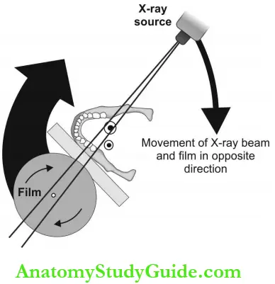
Armamentarium:
- X-ray tube head: Narrow fan-shaped X-ray beam.
- Positioning apparatus: Beam marker, chin-rest, lateral head supports, and bite block.
- Exposure parameters:
- kVp = 70-100
- mA = 4-12.
- Time: 18 seconds approximately.
- Exposure parameters:
- Focal trough or image layer: Three-dimensions curved zone within which structures are demonstrated. Objects placed anterior or posterior to it appears blurred.
- Patient positioning: Explain the procedure to the patient which are as follows:
- The patient is asked to remove all objects from the head and neck as they appear as ghost images.
- Sit or stand with the back straight and erect to prevent spine shadow bite on the disposable bite block.
- A lead apron is placed for radiation protection.
- The Frankfort plane should be parallel to the floor with the midsagittal plane perpendicular to the floor. The patient should remain still during the exposure.
- Film placement: A screen film is placed between two intensifying screens in a cassette. The cassette is placed in the cassette holder which moves around the patient.
Read And Learn More: Oral Medicine and Radiology Question And Answers
Panoramic Radiography Interpretation:
- Ideal Orthopantomogram: Teeth should be arranged with a smile, like an upward curve posteriorly, and be separated from each other. Posterior teeth should be uniform on both sides. Apices of the anterior should not be cut-off. The crown must not appear fractured.
- Mandible: Condylar and coronoid process, TMJ, ramus, body, and angle of the mandible, teeth, and supporting structures.
- Mid-facial region: Maxillary sinus, zygomatic complex, nasal cavity, and maxillary dentition.
- Soft tissue shadows: Earlobe, Soft palate, uvula, tonsils, tongue, posterior wall of pharynx, lip, cheek, nasolabial fold, and nose.
- Air shadows: Oropharynx, nasopharynx, maxillary sinus, nasal fossa.
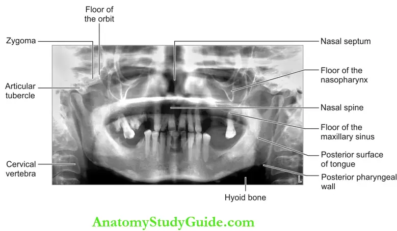
Panoramic Positioning Errors:
- The patient’s head is too far forward from the focal trough.
- Narrowing of anterior teeth.
- Cervical spine superimposition on Rami.
- The patient’s head is backward from the focal trough.
- Widening of the anterior teeth.
- TMJ is not clear.
Midsagittal plane positioning errors:
- The patient is tilted in the machine.
- A widened gap between upper and lower posterior teeth on one side.
- Condyle enlarged on one side.
- Enlarged mandible.
- Bony details appear fuzzy.
Occlusal plane positioning errors
- Chin tipped too low: (Frankfort plane down-ward).
- The smile line is exaggerated.
- Apices of mandibular anterior are cut off.
- Chin tipped too high: (Frankfort plane up-ward).
- Reverse smile line.
- The hard palate and floor of the nasal cavity superimpose over the maxillary teeth roots.
- Blurred maxillary incisors.
Panoramic Artifacts:
- Ghost image: Objects located between the X-ray source and behind the center of rotation produce ghost images, for example, the spine, neck chains, and horns of the hyoid produce ghost images.
- Double image: Midline structures like the turbinate of the nose, the body of the hyoid, and the spine produce a double image.
Panoramic Indications:
- To examine:
- The extent of lesions.
- The eruption pattern, growth, and developments.
- Multiple impacted teeth.
- Cysts and tumors.
- Jaw fracture.
Panoramic Contraindications:
- Routine screening.
- Periodontal assessment of pocket less than 5 mm.
- As an alternative to intraoral radiographs.
Panoramic Advantages:
- Radiation dosage is about 1/3rd of the dose from the full mouth survey.
- A large area is imaged.
- Preorthodontic assessment of periodontal status.
- For the record and reference purposes.
Panoramic Disadvantages:
- Structures located outside the focal trough cannot be assessed accurately.
- Shadow of soft tissues superimpose the hard tissue and reduces the accuracy.
- The overall magnification in panoramic radiographs is 15-20%.
- Resolution, sharpness, and contrast is low compared to intraoral radiographs.
Question 2. Enumerate the various skull radiographic projections and explain in detail the PA skull projection.
Answer:
- Skull Projections: They are PA skull projection, lateral skull projection, Waters’ projection, and submental- vertex projection.
- Equipment: Skull projections are taken in an extraoral radiographic machine called a cryostat or cephalogram. X-ray source, grid, and cassette must be labeled R or L before exposure (screen film is used). The patient positioning table with exposure parameters (kVp and mA) is different for each projection.
- PA Skull Projection: X-ray beam passes in the posterior to the anterior direction through the skull.
- Equipment Preparation: The radiographic machine used is a cephalogram with a grid. The cassette must be labeled R or L prior to exposure. Exposure parameters: 70 kVp and 30-50 mA are commonly preferred.
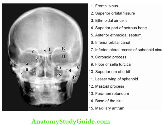
Skull Patient Positioning:
- The patient is positioned to face the cassette such that the forehead and nose touch the cassette.
- The head is centered over the cassette such that the midsagittal plane is perpendicular to the floor and the Frankfort plane is parallel to the floor and perpendicular to the film.
Skull Film Placement:
- A screen film size of 8 x 10 inches or 20 x 25 cm is used. The cassette is placed perpendicular to the floor in the cassette-holding device.
- The long axis of the cassette is positioned vertically facing the patient.
Skull Projection of Central Beam:
- The central beam is directed perpendicular to the film plane coincident with the midsagittal plane of the patient at the level of the bridge of the nose.
- The distance between the X-ray source and the midsagittal plane should be approximately 5 feet (60 inches) and the film is placed 15 cm away from the midsagittal plane.
Skull Indications:
- Examination of the skull for growth and development, trauma, disease, and developmental abnormalities.
- For evaluation of facial structures including frontal and ethmoidal sinuses, nasal fossa, and orbits.
Question 3. Discuss mandibular lateral oblique projection in detail.
(or)
Describe the extraoral radiographic technique that is best indicated to view the large lesions in the mandible. Explain the technique and indications of the various views of the same projection in detail.
Answer:
Mandibular Lateral Oblique Projection: It is used to examine large lesions in the mandible which cannot be covered in the periapical radiograph and when higher resolution is required than panoramic projection. Two projections are depending upon the region of the lesion.
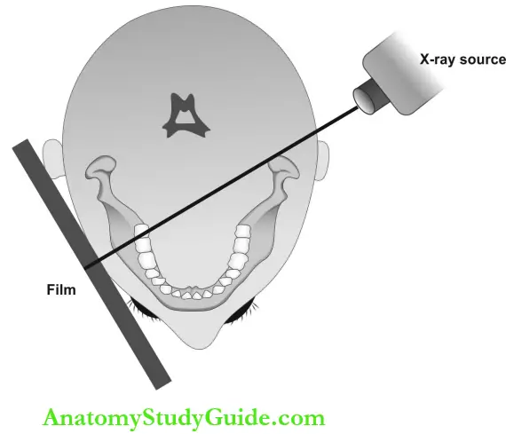
- Body of the mandible projection: It demonstrates the premolar and molar region and inferior border of the mandible.
- Equipment preparation: Exposure parameters: 65 kVp, 10 mA, and H seconds. It can be taken in the intraoral radiographic machine. If a cephalogram is used, an open-ended aiming cylinder is used.
- Patient positioning: The head is tilted to the side of the examination, and the mandible is protruded to avoid spine superimposition.
- Film placement: Around 5 x 7” screen film is used. The patient should position the cassette on the cheek region centered over the lower first molar. The lower border of the cassette should be in the plane of the inferior border of the mandible and extend 2 cm below the inferior border.
- Projection of central beam: Central beam is perpendicular to a film directed from a point 2 cm below the angle of the mandible on the tube side towards the first molar region.
Mandibular Lateral Oblique Projection Indications:
- To view the mediolateral extent of large lesions like cysts and tumors in the mandibular body region.
- To examine fractures in the body of the mandible.
- For evaluation of sialolith in submandibular gland duct.
Ramus Projection: It demonstrates the ramus from the angle of the mandible to the condyle and third molar region of both the maxilla and mandible.
- Equipment preparation: Exposure parameters: 65 kVp, 10 mA, and 1/4 seconds. It can be taken in the intraoral radiographic machine. If cephalogram is used, an open-ended aiming cylinder is used.
- Patient positioning: The head is tilted towards the side being examined, and the mandible is protruded to avoid spine superimposition.
- Film placement: 5 x 7 inches (13 x 18 cm) screen film is used. The patient should keep the cassette on the cheek region centered over the ramus and far enough posteriorly to include the condyle. The lower border is parallel and extends 2 cm beneath the lower border of the mandible.
- Projection of central beam: Central beam is perpendicular to the film and directed from a point 2 cm beneath the lower border of the mandible in the first molar region on the tube side towards the ramus region on the side of interest.
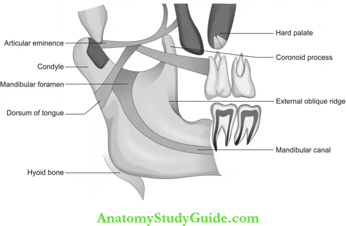
Ramus Projection Indications:
- To view the mediolateral extent of large lesions like cysts and tumors in the ramus and posterior most region of the mandible.
- To evaluate fractures in the ramus of the mandible.
- For evaluation of sialolith.
- Assessment of the presence and position of impacted teeth.
Extraoral Radiographic Techniques Short Notes
Question 1. Discuss the merits and demerits of OPG.
Answer:
OPG Advantages:
- Radiation dosage is about 1/3rd of the dose from the full mouth survey.
- Provide diagnostic details of teeth and supporting structures of both jaws.
- Simplicity: Minimal amount of time and training for the dental radiographer.
- Accurate assessment of the dimension of lesions involving a posterior region of the mandible when margins are well-defined.
- Bilateral condyle lesions and other parts of the mandible seen in one film facilitate comparative study.
- Preorthodontic, presurgical assessment, and for initial evaluation of generalized periodontal status.
- For documentation, record, and reference purposes.
OPG Disadvantages:
- Structures present outside the focal trough may not be evident.
- Soft tissue shadow overlies the required hard tissue structures and reduces accuracy.
- The overall magnification obtained in panoramic radiographs is 15-20%.
- Resolution, sharpness, and contrast are low as compared to intraoral radiographs.
- Some patients do not conform to the shape of the focal trough, and as a result, some structures are out of focus.
- Intensifying screens result in a loss of image quality.
- Dental caries, periodontal status, bone loss, and periapical pathosis are not seen with clarity.
- Technique is sensitive, hence positioning errors to result in faulty radiographs.
- Cannot be used for evaluation of the buccolingual extent of a lesion.
Question 2. Describe Waters’ projection.
Answer:
- Occipitomental projection (0° and 30°)
- Variation of PA projection.
Equipment Preparation (0° and 30°):
- The radiographic machine used is a cephalogram with a grid to prevent scattered radiation and improve contrast.
- Cassette: It must be labeled R or L before exposure. Exposure parameters: Usually 70 kVp and 100 mA are the recommended parameters.
Patient Positioning (0° and 30°):
- The head is positioned such that the midsagittal plane is perpendicular to the film plane. The patient should be positioned to face the film and in a head tilted back direction so that the canthomeatal line is at 45° to the cassette with the nose and chin touching the cassette.
- If the sphenoidal sinus should be projected onto the film plane, the patient is instructed to open the mouth.
Waters’ projection Film Placement: 8 x 10 inch (20 x 25 cm) screen film is used. The cassette is placed perpendicular to the floor in the cassette-holding device. The long axis of the cassette is positioned vertically facing the patient.
Projection of Central Beam (0° projection): Central beam is directed horizontally 0° coincident with the midsagittal plane of the patient at the level of the maxillary sinus through the occipital.
For 30° projection: The direction of the central beam is downward from above the head and at 30° horizontal to the lower border of the orbit.
Indications For 0° projection:
- This projection is mainly for the investigation of the maxillary antrum and facial skeleton.
- For the detection of midfacial fractures:
- Le Fort 1
- Le Fort 2
- Le Fort 3
- Zygomatic complex
- Nasoethmoidal complex
- Orbital blow-out.
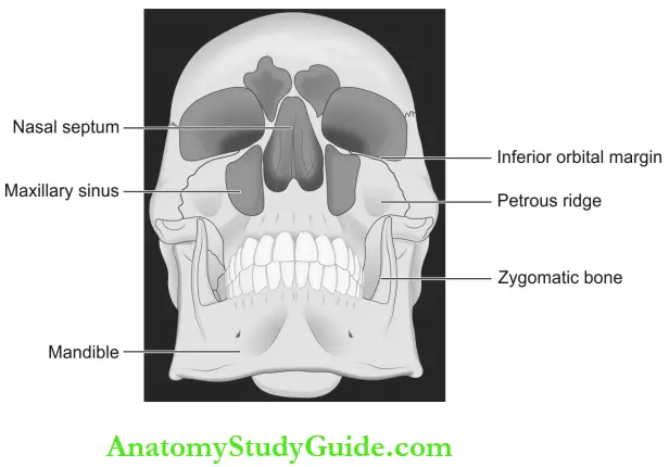

For 30°projection:
- This projection enables the diagnosis of certain bony displacements.
- For the detection of midfacial fractures:
- Le Fort 1
- Le Fort 2
- Le Fort 3
- Coronoid process fractures.
- Both (0°-and 30° projections) are indicated to diagnose the suspected facial fracture but at different angles.
Question 4. Explain submentovertex projection.
Answer: This view reveals structures including the base of the skull, sphenoidal sinuses, and the facial bones from below. Also called base or full axial projection and it is an anteroposterior projection.
- Submentovertex projection Equipment Preparation: The radiographic machine used is a cephalogram with a grid. Cassette: It must be labeled R or L before exposure. Exposure parameters: 70 kVp and 100 mA.
- Submentovertex projection Patient Positioning: Head and neck extended backward as possible such that the vertex of the skull touches the center of the cassette. The patient’s midsagittal plane is perpendicular to the floor and the Frankfort plane is vertical and parallel to the floor with canthomeatal line should extend 10° past the vertical.
- Submentovertex projection Film Placement: 8 x 10 inch (20 x 25 cm) screen film is used. The film cassette is placed in the vertical direction behind the patient’s head and should be centered over the skull vertex.
- Submentovertex projection Projection of Central Beam: Central beam is directed from below the mandible upward towards the vertex of the skull and is positioned far enough anterior to pass about 2 cm in front of a line connecting right and left condyles.
Submentovertex projection Indications:
- Bony lesions involving the palate, pterygoid region, and the base of the skull.
- Examination of the sphenoidal sinus.
- Evaluation of the lateral wall of the maxillary antrum.
- Assessment of the thickness of the posterior mandible in mediolateral direction before surgical procedures.
- The less exposure parameters used in submentovertex view reveal the fracture of the thin zygomatic arches accurately. The SMV taken with reduced exposure factors is called the jughandle view.
Question 5. Explain lateral skull projection.
Answer:
Lateral skull projection Equipment Preparation: The radiographic machine used is a cephalogram with a grid. Exposure parameters: 70 kVp and 100 mA.
Lateral skull projection Patient Positioning: The side of interest (right or left) of the patient’s head is positioned and centered over the cassette. The midsagittal plane of the patient is parallel to the cassette and perpendicular to the floor.
Lateral skull projection Film Placement: 8 x 10 inch (20 x 25 cm) screen film is used. Placed in the cassette holding device adjacent to the side of interest perpendicular to the floor.
Lateral Skull Projection of Central Beam: The central beam is directed through the external auditory meatus to the center of the cassette from the opposite side perpendicular to it.
Lateral skull projection Indications:
- Fractures of the cranium and the skull base.
- Midfacial fractures and the downward and backward displacement of the maxilla.
- Investigation of the frontal, sphenoidal, and maxillary sinuses.
- Conditions affecting the skull vault, like:
- Paget’s disease
- Multiple myeloma
- Hyperparathyroidism
- To examine sella turcica for:
- Pituitary gland tumor in acromegaly.
- Enlargement or ballooning of the seller.
Question 6. Explain cephalometric projection.
Answer: Cephalometric radiography is an extraoral radiographic technique that applies standar¬dized landmarks to predict the maxilla-mandibular jaw relations with the base of the skull and the occlusal relation of teeth for an orthodontic assessment.
Cephalometric radiography Indications:
- In orthodontics: Initial diagnosis and pre-operative evaluation, treatment planning and monitoring of treatment, and appraisal of treatment results.
- Before orthognathic surgery:
- Preoperative skeletal and soft-tissue evaluation.
- Postoperative assessment and term follow-up.
Cephalometric radiography Equipment: The equipment consists of a cephalogram with head positioners and ear rods, a cassette with a screen film of 18 x 24 cm. Aluminum- wedge filter between patient and cassette for attenuation of the X-ray beam in soft tissues. The X-ray source to film distance is 60 inches. The X-ray beam is collimated.
Cephalometric radiography Projections :
- PA Cephalometric:
- Technique and positioning:
- The head stabili¬zing device of the cephalogram is rotated through 90°. The patient is positioned in the radiographic unit with the head tilted in a forward direction.
- The head is immobilized by positioning the ear rods into the external auditory meatus. The central ray is horizontally directed through the cervical spine at the level of the rami of the mandible.
- Technique and positioning:
Cephalometric radiography Lateral Cephalometric:
-
- Technique and positioning:
- The patient is positioned within the cephalogram. The sagittal plane of the head should be vertical and parallel to the film and the Frankfort horizontal plane. Teeth should be in the maximum intercuspal position.
- The head is immobilized with the help of ear rods. The aluminum wedge is placed between the patient and the anterior part of the cassette to attenuate the X-ray beam selectively in the region of the soft tissues. This allows the soft tissue profile on the radiograph.
- Technique and positioning:
Cephalometric Planes, Angles, and Points:
- Planes: Frankfort horizontal plane, mandibular plane, maxillary plane and SN plane.
- Angles: SNA, SNB, ANB, maxillary incisal inclination and mandibular incisal inclination.
- Cephalometric points: Orbitale (Or), nasion (N), Sella (S), anterior nasal spine (ANS), subscale or point A, prosthion (Pr), infra- dental (Id), supramental or point B, pogonion (Pog), Jonathon (Gn), Menton (Me), gonion (Go), posterior nasal spine (PNS), articulate (Au), and portion (Po).
Question 7. Describe reverse Towne’s projection.
Answer: Towne’s projection is AP skull projection. Reverse Towne’s is opposite of Towne’s view and is a PA skull projection mainly indicated to examine condylar neck fractures.
- Towne’s projection Equipment Preparation: The radiographic machine used is a cephalogram with the grid. Exposure parameters: 70 kVp and 100 mA.
- Towne’s projection Patient Positioning: Head centered in front of the cassette with canthomeatal line oriented downward 25-30°. The patient is instructed to open the mouth as wide as possible to visualize the condyles.
- Towne’s projection Film Placement: The cassette is held on the holding device in front of the patient with the patient’s forehead touching the cassette.
- Towne’s projection Projection of Central Beam: The central beam is directed towards the film in the sagittal plane through the occipital bone from the opposite side of the cassette.
Towne’s projection Indications:
- High fractures of the condylar necks.
- Intracapsular fracture of the TMJ.
- Condylar hypoplasia and hyperplasia.
- To examine the articular surfaces of the condylar head.
- To reveal a medially displaced condyle.
- Pathology related to the posterolateral wall of the maxillary sinus.
Question 8. Briefly explain about PA view of the mandible.
Answer: This projection shows the mandibular posterior structures. It is a variant of the PA skull view but is not indicated for skull details as it allows the overlapping of the base of the skull and nasal bones.
- Mandible Equipment Preparation: The radiographic machine used is a cephalogram with a grid. The cassette must be labeled R or L before exposure. Exposure parameters: 70 KVp and 30-50 mA.
- Mandible Patient Positioning: The patient is positioned to face the cassette such that the forehead and nose touch the cassette. The head is centered over the cassette with the midsagittal plane perpendicular to the floor and the Frankfort plane parallel to the floor and perpendicular to the film.
- Mandible Film Placement: 8 x 10 inch (20 x 25 cm) screen film is used. The cassette is placed perpendicular to the floor in the cassette-holding device. The long axis of the cassette is positioned vertically facing the patient.
- Mandible Projection of Central Beam: Central beam is directed perpendicular to the cassette and through the cervical spine at the level of the ramus.
Projection of Central Beam Indications:
- Mandibular fractures involving the following:
- Posterior body
- Angle and rami of the mandible
- Lower condylar neck
- Cysts and tumors are mainly in the posterior third of the body or rami to see the mediolateral expansion.
- Mandibular hypoplasia or hyperplasia.
- Maxillofacial deformities.
Question 9. Describe the rotated PA view of the mandible.
Answer: It reveals details of the parotid gland and ramus of the mandible on one side of the face.
Rotated PA view of the mandible Technique: The patient is positioned facing the film such that tip of the nose is touching the film with an occlusal plane horizontally. The head is then rotated 10° to the side of interest to avoid the superimposition of the skull base. The central beam is projected in a horizontal (0°) direction on the side of interest.
Rotated PA view of the mandible Indications:
- To view sialolith in parotid glands.
- To see the mediolateral expansion of cysts or tumors in the ramus.
- To ensure new bone formation in submits- steric space infection.
Extraoral Radiographic Techniques Multiple Choice Questions
Question 1. Panoramic radiography is based on the principle of.
- Rotation
- Focal trough
- Tomography
- Image slicing
Answer: 3. Tomography
Question 2. Which of the following moves around the patient’s head in panoramic radiography?
- Film
- Film and X-ray machine
- X-ray tube head
- X-ray tube head and cassette
Answer: 4. X-ray tube head and cassette
Question 3. The three-dimensional zone in which structures are demonstrated in panoramic radiography is called.
- Cross-sectional image
- Focal trough
- Tomographic layer
- Image bandwidth
(Note: Focal trough or image layer).
Answer: 2. Focal trough
Question 4. A radiopaque artifact seen on the panoramic film produced by a radiopaque object that is penetrated twice by the X-ray beam is called.
- Double image
- Image superimposition
- Ghost image
- Image distortion
Answer: 3. Ghost image
Question 5. A reverse smile line in the panoramic film appears when the patient’s chin is positioned.
- Too low
- Too high
- Too close to source
- Away from the source.
(Note: Patient’s chin is positioned too high or Frankfort plane is placed upward).
Answer: 2. Too high
Question 6. An exaggerated smile line in the panoramic film appears when the patient’s chin is positioned.
- Too low
- Too high
- Too close to source
- Away from the source.
(Note: Patient’s chin is positioned too low or Frankfort plane is placed downward).
Answer: 1. Too low
Question 7. In panoramic radiography, when the patient is positioned too far forward on the bite block, anterior teeth appear.
- Widened and elongated
- Narrowed and foreshortened
- Spaced and blurred
- Narrowed and blurred
Answer: 4. Narrowed and blurred
Question 8. In panoramic radiography, when the patient is positioned too far back on the bite block, anterior teeth appear.
- Widened and elongated
- Narrowed and foreshortened
- Widened and blurred
- Narrowed and blurred
Answer: 3. Widened and blurred
Question 9. Which of the following projection is best indi¬cated to view the maxillary sinus?
- Jughandle view
- Water’s view
- Reverse Towne’s view
- Posteroanterior skull view
Answer: 2. Water’s view
Question 10. Which view is best indicated to view zygo¬matic arch fracture?
- Jughandle view
- Waters’ projection
- Reverse Towne’s view
- Posteroanterior skull view
(Note: Jughandle view or submentovertex view).
Answer: 1. Jughandle view
Question 11. Which view is best indicated to view condylar neck fracture?
- Jughandle view
- Waters’ projection
- Reverse Towne’s view
- Posteroanterior skull view
Answer: 3. Reverse Towne’s view
Question 12. Which extraoral view is indicated to view the frac¬ture of the body of the mandible is?
- Jughandle view
- Waters’ projection
- Reverse Towne’s view
- Lateral oblique view
Answer: 4. Lateral oblique view
Question 13. Which of the following projection is best for examination of the soft tissue profile of the face is?
- Jughandle view
- Waters’ projection
- Reverse Towne’s view
- Lateral cephalometric view.
Answer: 4. Lateral cephalometric view
Question 14. Base or full axial projection is named as.
- Jughandle view
- Submentovertex view
- Reverse Towne’s view
- Posteroanterior skull view
Answer: 2. Submentovertex view
Extraoral Radiographic Techniques Viva Voce
Question 1. What is a focal trough?
Answer:
- The three-dimensional zone in which structures are demonstrated in panoramic radiography is called the focal trough or image layer.
- Structures positioned anterior or posterior to the focal trough appears blurred.
- Closer the rotation centers to the teeth, the narrower the focal trough.
- The focal trough is narrower in the anterior region and wider in the posterior region.
Question 2. What is the jughandle view and when it is mainly indicated?
Answer:
- It is a submentovertex projection with reduced exposure time, and it is mainly indicated to view zygomatic arch fractures.
- Exposure time is reduced to one-third which is used to visualize the skull.
Question 3. What is PA projection?
Answer: The X-ray source is placed behind the patient such that the central beam is passed from structures posterior to anterior.
Question 4. What is AP projection?
Answer: The X-ray source is placed behind the patient such that the central beam is passed from structures anterior to posterior.
Question 5. What is a ghost image?
Answer: Objects located between the X-ray source and behind the center of rotation produce ghost images.
Ghost image Examples:
- The ghost image of the palate superimposes on apices of maxillary teeth as a wide radiopaque line.
- The spine, neck chains, and horns of hyoid bone produce ghost images.
- Ghost images have the same shape as its counterpart and it appears on opposite side. It appears higher up and is blurred.
Question 6. What is the reason for double images in OPG?
Answer:
- Double images occur in the central portion of the OPG where objects are intercepted twice by the beam.
- Midline objects like the turbinate of the nose, the body of the hyoid, and the spine produce a double image.
Question 7. What are the extraoral film sizes available?
Answer:

Question 8. Why is a thyroid collar not recommended for panoramic imaging?
Answer: The thyroid collar absorbs the central rays and obscures the diagnostic information.
Question 9. What happens when the patient is not instructed about lip and tongue position during panoramic exposure?
Answer: The patient should close the lips and position the tongue on the palate during exposure.
Failure to follow this step will lead to:
- A dark radiolucent band will be seen above the apices of maxillary teeth.
- Diagnostic information of the periapical region of maxillary teeth will be obscured.
Question 10. What happens when the patient is not standing perfectly straight in panoramic radiography?
Answer: Radiopaque shadow of the spine is seen in the midline of the film.
Question 11. What are the different AP projections of the skull?
Answer:
- Submentovertex projection.
- Towne’s projection.
Question 12. What is Towne’s projection?
Answer:
- The Towne’s view is AP projection and is often of value in assessing the status of the condyles, condylar neck, and rami because superimposition of the mastoid and zygoma over the condylar neck region in the straight posteroanterior projection often makes interpretation difficult.
- The Towne’s view eliminates this super-imposition and ensures better visualization of the condylar area and rami.
- The patient lies on his back with the film under his head. The X-ray source is from the front but rotated 30% from the Frankfort plane and is directed right at the condyles.
Extraoral Radiographic Techniques Highlights
-
- Extraoral radiograph techniques refer to methods of obtaining skull and maxilla-mandibular images. The film is placed in a cassette and used in paired with intensifying screens. The single film provides greater diagnostic details and helps the dentist to precisely localize the extent of bony lesions and also to predict the generalized osseous deformities in association with dental structures.
- There are many types of extraoral radiographs. Some types are used to view the entire skull, whereas other types are focused on the maxilla and mandible.
Leave a Reply