Working Length Determination Introduction
Determination of accurate working length and its maintenance during cleaning and shaping procedures are key factors for successful endodontic treatment. The cleaning, shaping, and obturation cannot be accomplished accurately unless the working length is determined correctly.
Table of Contents
Thus, predictable endodontic success demands an accurate working length determination of the root canal. The procedure for establishment of working length should be performed with skill, using techniques which have shown to give valuable and accurate results and are practical and successful.
Read And Learn More: Endodontics Notes
Working Length Determination Definitions
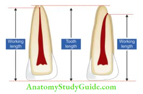
According to the endodontic glossary, the working length is defined as “the distance from a coronal reference point to a point at which canal preparation and obturation should terminate”.
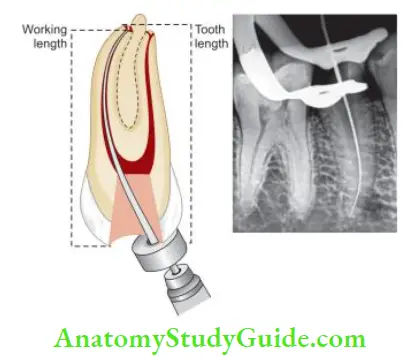
Reference point:
The reference point is the site on the occlusal or the incisal surface from which measurements are made.
- It should be stable and easily visualized during the preparation
- Usually, it is the highest point on the incisal edge of anterior teeth and the buccal cusp of posterior teeth
- It should not change between the appointments. Therefore to have a stable reference point, undermined cusps and restorations should be reduced before access preparation
- The anatomic apex is the “tip or end of root determined morphologically.”
- The radiographic apex is the “tip or end of root determined radiographically.”
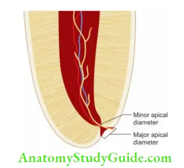
- The apical foramen is the main apical opening of the root canal which may be located away from the anatomic or radiographic apex.
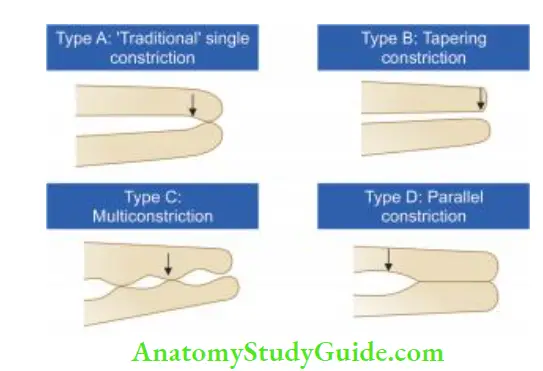
- Apical constriction (minor apical diameter) is the apical portion of the root canal having the narrowest diameter. It is usually 0.5–1 mm short of the apical foramen. The minor diameter widens apically to the major diameter (apical foramen). Dummer classifies apical constriction as four types which need to be analyzed to prevent over and under-instrumentation.
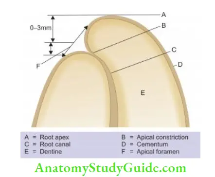
- Cementodentinal junction (CDJ) is the region where the cementum and dentin are united, the point at which the cemental surface terminates at or near the apex of a tooth.
- It is not always necessary that CDJ always coincide with apical constriction.
- The location of CDJ ranges from 0.5 mm to 3 mm short of the anatomic apex.
Historical Perspectives:
Significance Of Working Length
- The working length determines how far into the canal instruments can be placed and worked.
- If placed within correct limits, it plays an important role in determining the success of the treatment
- It affects the degree of pain and discomfort the patient will experience during or after the treatment.
- If proper care is not taken, over or under-instrumentation can occur.
Consequences of over-instrumentation:
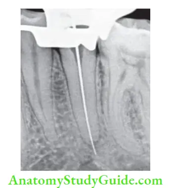
Over-instrumentation means an extension of instruments into periapical tissue beyond apical constriction. It may cause
- Pain as a result of acute inflammatory response from mechanical damage to the periapical tissue
- In infected teeth, over-instrumentation leads to the extrusion of microbes and infected debris which aggravate the inflammatory responses in the periapical tissue
- Overfilling that causes a mechanical and chemical irritation of the periapical tissue along with foreign body reaction
- Prolonged healing time and lower success rate because of incomplete regeneration of cementum, periodontal ligament, and alveolar bone
Consequences of under-instrumentation:
- Underinstrumentation is working to a level shorter than the actual length, leaving the apical part of the canal without proper instrumentation. It may cause:
- Accumulation of infected debris apically which impairs or prevents healing
- Incomplete apical seal which supports the existence of viable bacteria resulting in poor prognosis of the treatment
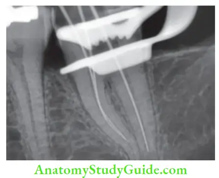
Working Width
Working width is defined as “initial and post-instrumentation horizontal dimensions of the root canal system at working length and other levels.”
The minimum initial working width corresponds to the initial apical file size which binds at working length. Maximum file working width corresponds to the master apical fie size.
Definitions:
- MinIWW(N): Minimal initial horizontal dimension N mm short of working length
- MinIWW0: Minimal initial horizontal dimension at working length
- MaxIWW(N): Maximal initial horizontal dimension N mm short of working length
- MaxIWW0: Maximal initial horizontal dimension at working length
Traditional Concept:
For many years, two guidelines were considered for instrumentation:
- Enlarge the root canal at least three sizes beyond the first instrument that binds the canal
- Enlarge the canal until it is clean. It is indicated by white dentinal shavings on the instrument flies
However, these guidelines are not considered the sole criteria in all cases. The color of dentinal shavings is not an indication of the presence of infected dentin.
An ideal enlargement should provide debris removal throughout the canal and facilitate irrigation to the level of minor constriction. Final apical firing should not cause any apical transportation.
Current Concept:
Ideally, the master apical file, that is, the final file of the prepared canal cannot be standardized and it varies according to different cases. Nowadays, the use of NiTi rotary files with greater taper allows irrigants to reach the apical third more effectively, so it is always recommended to prevent over-enlargement of minor constriction.
It can result in increased chances of preparation errors like extrusion of irrigants, obturating material, etc.
The final enlargement of the canal depends on the following factors:
- Gauging of the canal: Initial canal width guides to a large extent the master apical file. If the gauging fie is 10 N, the apex cannot be prepared to No. 60 MAF
- Presence or absence of periarticular pathology
- The vitality of the pulp
- Canal configuration like degree of curvature, C-shaped canal, etc.
Directional Stop Attachments:
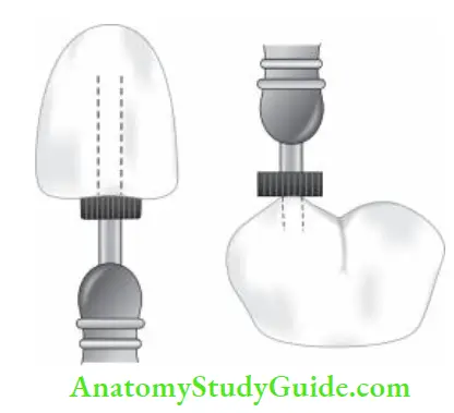
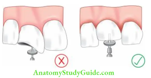
- The most commonly used stoppers for endodontic instruments are silicon rubber stops, though stop attachments can be made up of metal, plastic, or silicon rubber
- Stop attachments are available in teardrop or round shapes
- Irrespective of shape, the stop should be placed perpendicular to the instrument not at any other direction (oblique) so as to avoid variation in working length
- The advantage of using a tear-shaped stopper is that in the curved canal, it can be used to indicate the canal curvature by placing its apex toward the direction of the curve
Different Methods Of Working Length Determination
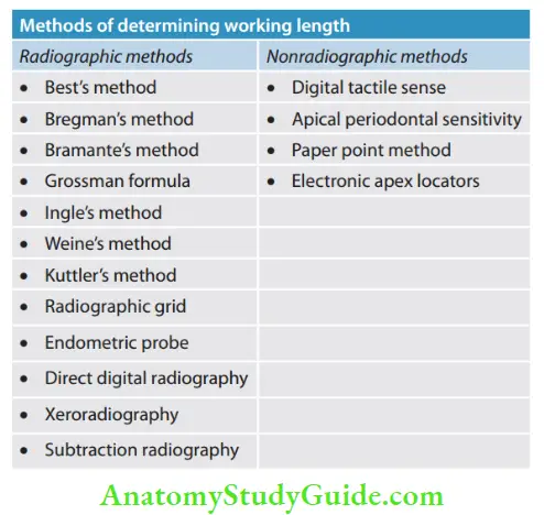
Radiographic Method Of Working Length Determination
Radiographic apex has been used as the termination point in working length determination for many years and it has shown promising results. However, there are two schools of thought regarding this:
Those who follow this concept say cementodentinal junction is impossible to locate clinically and the radiographic apex is the only reproducible site available for length determination. According to it, a patent root tip and larger files kept within the tooth may result in an excellent prognosis.
Those who do not follow this concept say that the position of the radiographic apex is not reproducible. Its position depends on a number of factors like angulation of the tooth, the position of the film, film holder, length of the X-ray cone, and presence of adjacent anatomic structures, etc.
When radiographs are used in determining working length, the quality of the image is important for accurate interpretations. Among the two commonly used techniques, the paralleling technique has been shown to be superior compared to bisecting angle technique in the determination and reproduction of apical anatomy.
As the angle increases away from parallel, the quality of the image decreases. This occurs because as the angle increases, the tissue that X-rays must pass through includes a greater percentage of bone mass, therefore, the root anatomy becomes less apparent.
Different Methods Of Working Length Determination Clinical Tips:
- When two superimposed canals are present (e.g., buccal and palatal canals of the maxillary premolar, and mesial canals of the mandibular molar), one should take the following steps:
- Take two individual radiographs with an instrument placed in each canal
- Take radiograph at different angulations, usually 20–40° at a horizontal angulation
- Insert two diffrent instruments, e.g., K fie in one canal, H fie/reamer in other canal, and take radiograph at diffrent angulations
- Apply the SLOB rule; expose tooth from mesial or distal horizontal angle; canal which moves to the same direction is lingual, whereas canal that moves to the opposite direction is buccal
- In curved canals, canal length is reconfirmed because the final working length may shorten up to 1 mm as the canal is straightened out by instrumentation
Different Methods Of Working Length Determination Advantages:
- The anatomy of the tooth and curvature of a root canal can be seen on a radiograph
- Radiograph helps in analyzing the relationship between adjacent teeth and anatomic structures.
Different Methods Of Working Length Determination Disadvantages:
- Varies with different observers
- Superimposition of anatomical structures
- Two-dimensional view of a three-dimensional object
- Cannot interpret if apical foramen has buccal or lingual exit
- Risk of radiation exposure
- Time-consuming
- Limited accuracy
Different Methods Of Working Length Determination Clinical Tips:
Orthophotography (OPG) radiographs are not advocated for calculating tentative working length because gross magnification of 13–28% employed in OPG may lead to errors in the calculation of accurate readings.
Best Method:
It was introduced in 1960 by Best. In this, a steel 10 mm pin is fied to the labial surfaces of the root with utility wax, keeping it parallel to the long axis of the tooth
- Radiograph is taken and measurements were made using a gauge
Bregman’s Method:
- In this, 25–mm length flt probes are prepared which have a steel blade filled with acrylic resin as a stop, leaving a free end of 10 mm for placing in the root canal
- After this, a radiograph is taken and the working length is measured using the following formula:
- RLT = RLI × ALT/ALI
- RLT: Real length of the tooth
- RLI: Real length of the instrument
- ALT: Apparent length of the tooth
- ALI: Apparent length of the instrument
Bramante’s Method:
- It was introduced in 1974. Here, stainless steel probes are used, which are bent at a right angle at one end that is inserted into acrylic resin
- The probe is placed in the canal such that resin touches the cusp tip and the bent part of the probe is parallel to the mesiodistal diameter of the crown so that it can be seen on a radiograph
- On the radiograph, the following reference points are made:
- A: Internal angle of intersection of incisal and radicular probe segment
- B: Apical part of the probe
- C: Apex of tooth
Now the working length is calculated in two ways:
1. From the radiograph, AB (radiographic length of probe) and AC (radiographic length of the tooth), and the actual length of the probe are measured and the working length of the tooth is calculated using the following equation:
- CRD = CRS × CAD/CAS
- CRD: Real tooth length
- CRS: Real probe length
- CAD: Radiographic tooth length
- CAS: Radiographic probe length
2. Measure the distance between the apical end of the probe and the radiographic apex and add or subtract accordingly that can be the correct working length
Grossman Method/Mathematical Method of Working Length Determination
It is based on simple mathematical formulations to calculate the working length. In this, an instrument is inserted into the canal, the stopper is fied to the reference point and a radiograph is taken. Th formula to calculate the actual length of the tooth is as follows:
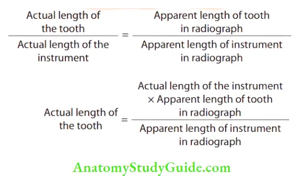
In the formula, three variables are known and by applying the formula, the fourth variable, that is, the actual length of the tooth can be calculated.
Ingle’s Method of Length Determination:
- Before access opening, fractured cusps, cusps weakened by caries, or restorations are reduced to avoid the fracture of weakened enamel during the treatment. This will avoid the loss of the initial reference point and thus the working length
- Measure the estimated working length from the preoperative periapical radiograph
- Adjust the stopper of the instrument to this estimated working length and place it in the canal up to the adjusted stopper
- Take the radiograph
- On the radiograph, measure the difference between the tip of the instrument and the root apex. Add or subtract this length to the estimated working length to get the new working length
- The correct working length is finally calculated by subtracting 1 mm from this new length
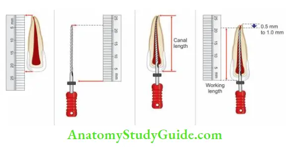
- (A) Measure the estimated working length from the preoperative radiograph
- (B) Adjust the stopper of the instrument to this length;
- (C) place it in the canal up to the adjusted stopper;
- (D) Take the radiograph and measure the difference between the tip of the instrument and the root apex. Add or subtract this length to the estimated working length to get the new length
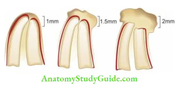
Weine’s Modification:
- Weine modified the calculation of working length according to the presence or absence of resorption as given below
- No resorption – subtract 1 mm
- Periapical bone resorption – subtract 1.5 mm
- Periapical bone + root apex resorption – subtract 2 mm
Kuttler’s Method:
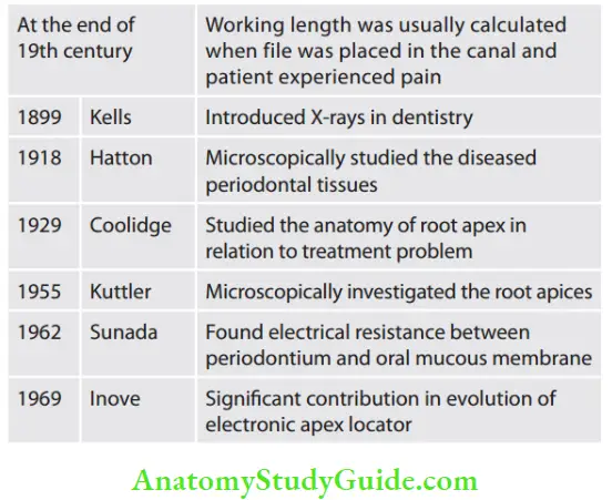
In 1955, Kuttler described apical areas from both the anatomic and histological points of view. He discussed and explained dentinocemental junction (DCJ), anatomic apex, and apical foramen.
DCJ is explained histologically but not clinically. The anatomic apex is the apex of the tooth and is just a geometric reference. Apical Constriction (Minor Diameter) is the narrowest part of the root canal short of the apical foramina or radiographic apex.
The apical foramen (Major diameter) is the main apical opening of the root canal through which blood vessels enter the canal. Its diameter is almost double the apical constriction giving it a funnel shape appearance, which has been described as morning glory or hyperbolic.
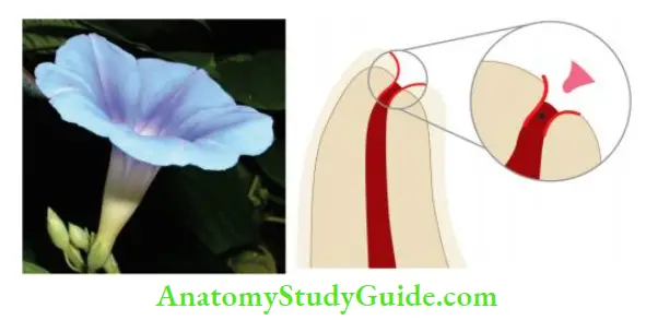
Apical foramen may not always be located at the center of the apex. It may exit mesial, distal, buccal, or lingual. According to Kuttler, canal preparation should terminate at apical constriction (minor diameter).
Technique:
- Locate minor and major diameters on the preoperative radiograph
- Estimate length of roots from preoperative radiograph
- Estimate canal width on the radiograph. If the canal is narrow, use a 10 or 15-size instrument. If it is of average width, use 20 or 25-size instruments. If the canal is wide, use 30 or 35 size instrument
- Insert the selected fit in the canal up to the estimated canal length and take a radiograph
- If the file is too long or short by >1 mm from minor diameter, readjust the fie and take a second radiograph
- If the file reaches major diameter, subtract 0.5 mm from it for younger patients and 0.67 for older patients
Kuttler’s Method Advantages:
- Minimal errors
- Has shown many successful cases
Kuttler’s Method Disadvantages:
- Time consuming and complicated
- Requires excellent quality radiographs
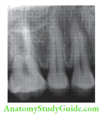
Radiographic Grid:
- It was designed by Everett and Fixott in 1963. It is a simple method in which a millimeter grid is superimposed on the radiograph
- This overcomes the need for calculation
- But it is not a good method if the radiograph is bent during exposure
Endometric Probe
- In this method, one uses the graduations on diagnostic fie which are visible on the radiograph
- But its main disadvantage is that the smallest fit size to be used is number 25
Direct Digital Radiography:
Here, the digital image is formed which is represented by a spatially distributed set of discrete sensors and pixels.
Two types of digital radiography:
- Radiovisiography
- Phosphor imaging system
Xeroradiography:
- It is a new method for recording images without film in which the image is recorded on an aluminum plate coated with selenium particles
- The plate is removed from the cassette and subjected to relaxation which removes old images, then these are electrostatically charged and inserted into the cassette
- Radiations are projected on film which causes the selective discharge of the particles
- This forms the latent image and is converted to a positive image by a process called “development” in the processor unit
Xeroradiography Advantages:
- This technique offers “edge enhancement” and good detail
- Ability to have both positive and negative prints together
- Improves visualization of fies and canals
- It is two times more sensitive than conventional D-speed films
Xeroradiography Disadvantages:
- Since saliva may act as a medium for flow of current, the electric charge over the film may cause discomfort to the patient
- Exposure time varies according to the thickness of the plate
- The process of development cannot be delayed beyond 15 min
Nonradiographic Methods Of Working Length Determination
Digital Tactile Sense:
In this, the clinician may see an increase in resistance as the fie reaches the apical 2–3 mm.
Digital Tactile Sense Advantages:
- Time-saving
- No radiation exposure
Digital Tactile Sense Disadvantages:
- Does not always provide the accurate readings
- In the case of narrow canals, one may feel increased resistance as fie approaches apical 2–3 mm
- In the case of teeth with immature apex, the instrument can go periodically
Apical Periodontal Sensitivity Test:
- This method is based on the patient’s response to pain
- But this method does not always provide the accurate readings
- For example, in the case of narrow canals, the instrument may feel increased resistance as fie approaches apical 2–3 mm and in the case of teeth with immature apex, the instrument can go beyond the apex
- In the cases of a canal with necrotic pulp, the instrument can pass beyond apical constriction, and in the case of vital or inflamed pulp, pain may occur several mm before the periapex is crossed by the instrument
Paper Point Measurement Method:
- In this method, a paper point is gently passed in the root canal to estimate the working length
- It is most reliable in cases of open apex where apical constriction is lost because of perforation or resorption
- The moisture of blood present on the apical part of the paper point indicates that the paper point has passed beyond the estimated working length
- It is used as a supplementary method
Electronic Apex Locators:
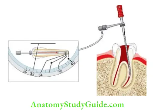
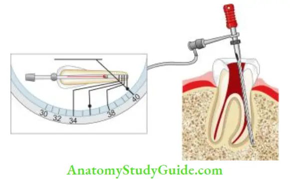
An electronic apex locator (EAL) is used to locate the apical constriction or cementodentinal junction, or apical foramen, but not the radiographic apex. Hence, the term apex locator is a misnomer. The ability to distinguish between the minor diameter and major diameter of the apical terminus is the most important for the creation of an apical control zone.
An apical control zone is a mechanical alteration of the apical terminus of the root canal space which provides resistance and retention form to the obturating material against the condensation pressure of obturation.
Components of EALs:
- Lip clip
- File clip
- Electronic device
- The cord which connects above three parts
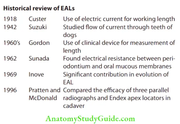
Advantages of apex locators:
- Provide objective information with a high degree of accuracy
- Accurate in reading (90–98% accuracy)
- Some apex locators are also available in combination with pulp tester and can be used to test pulp vitality
Disadvantages of apex locators:
- Can provide inaccurate readings in the following cases:
- Presence of pulp tissue in the canal
- Too wet or too dry canal
- Use of narrow fie
- Blockage of canal
- Incomplete circuit
- Low battery
- Chances of overestimation
- This may pose problems in teeth with immature apex
- Incorrect readings in teeth with periapical radiolucencies and necrotic pulp associated with root resorption, etc. because of lack of viable periodontal ligament
Uses of apex locators:
- Provide objective information with a high degree of accuracy
- Useful in conditions where the apical portion of the canal system is obstructed by
- Impacted teeth
- Zygomatic arch
- Tori
- Excessive bone density
- Overlapping roots
- Shallow palatal vault
- Useful in patients who cannot tolerate X-ray film placement because of gag reflex
- Useful in pregnant patients, to reduce the radiation exposure
- Useful in children who may not tolerate taking radiographs, disabled patients, and patients who are heavily sedated
- Valuable tool for
- Detecting site of root perforations
- Diagnosis of external and internal resorption which have penetrated root surface
- Detection of horizontal and vertical root fracture
- Determination of perforations caused during post preparation
- Testing pulp vitality
Contraindications to the use of apex locator:
Older apex locators were contraindicated in the patients who have cardiac pacemaker functions. Electrical stimulation to such patients could interfere with pacemaker function. But this problem has been overcome in the newer generation of apex locators.
Classification of EALs:
McDonald1 classified apex locators on the basis of the type of current flow as follows:
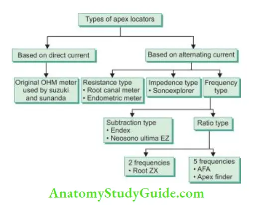
Classification According to Generations of EALs (Evolution of EALs)
1. First-generation apex locator (resistance apex locator)
- It is also known as resistance apex locator which measures opposition to the flow of direct current, that is, resistance
- It is based on the principle that resistance offered by the periodontal ligament, and the oral mucous membrane is the same, that is, 6.5 kΩ
- Examples of 1st generation apex locators are root canal meters, endometriotic meters (Onuki Medical Co., Japan), Dentometer, and Endo Radar.
Technique for Using Resistance-Based EAL:
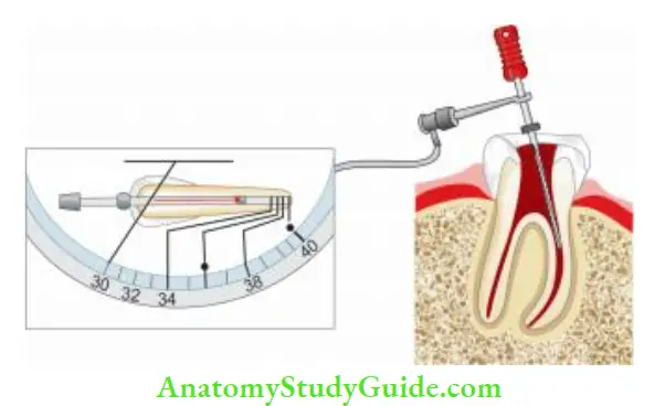
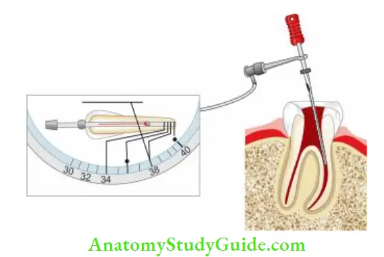
- Turn on the device and attach the lip clip near the arch being treated. Hold a 15-number file and insert it approximately 0.5 mm into the sulcus of the tooth (like a periodontal (PD) probe). Adjust the control knob until the reference needle is centered on the meter scale and produces audible beeps. Note this reading
- Using a preoperative radiograph, estimate the working canal width. Clean the canal if bleeding from vital pulp is excessive, and dry it with paper points
- Insert the file into the canal unless the reference needle moves from the extreme left to the center of the scale and the alarm beeps sound. Reset the stop at the reference point and record the lengths
- Take the radiograph with fie in place at the length indicated by the apex locator. If the length is longer/shorter, it is possible that the preoperative film can be elongated or the apex locator is inaccurate
First-generation apex locator Advantages:
- Easily operated
- Digital readout
- Audible indication
- Detect perforation
- Can be used with K-fie
- May incorporate pulp tester
First-generation apex locator Disadvantages:
- Requires a dry field
- Patient sensitivity
- Requires calibration
- Requires good contact with lip clip
- Cannot estimate beyond 2 mm
- The file should fi snugly in the canal
- The file should not contact metal restorations
2. Second-generation apex locator (impedance-based apex locator)/low-frequency apex locator
- Inoue introduced the concept of an impedance-based apex locator which measures opposition to the flow of alternating current or impedance
- This apex locator indicates the apex when two impedance values approach each other. Examples of second-generation apex locators are:
- Sonoexplorer
- Apex finder
- Exact-A-Pex
- Endoanalyzer (combination of apex locator and pulp tester)
- Digipex (has digital LED indicator but requires calibration)
Second-generation apex locator Advantages:
- Does not require a lip clip
- No patient sensitivity
- Analog meter
- Detects perforations
Second-generation apex locator Disadvantages:
- No digital readout
- Difficult to operate
- The canal should be free of electroconductive irrigants and tissue fluids
- Requires coated probes
- Cannot use Fies
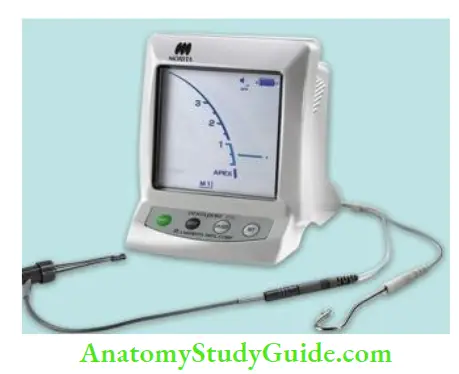
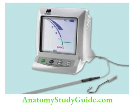
3. Thrd-generation apex locator/high-frequency apex locator
- It is based on the fact that different sites in the canal give differences in impedance between high (8 kHz) and low (400 Hz) frequencies
- The difference in impedance is least in the coronal part of the canal
- As the probe goes deeper into the canal, the difference increases
- It is the greatest at the cementodentinal junction
- Since the impedance of a given circuit may be substantially influenced by the frequency of current flow, these are also known as frequency-dependent
- More appropriately, they should be termed as “comparative impedance” because they measure relative magnitudes of impedance which are converted into length information. Various third-generation apex locators are:
- Endex (Original third-generation apex locator)
- Neosomo ultimo EZ apex locator
- Mark V plus
- Root ZX
- Root ZX II
- Root ZX mini
- Endo analyzer 8005
- Apex pointer
- Apex Finder
Third-generation apex locator/high-frequency apex locator Advantages:
- Easy to operate
- Uses K-type file
- Audible indication
- Can operate in the presence of fluids
- Analog readout
Third-generation apex locator/high-frequency apex locator Disadvantages:
- Requires lip clip
- Chances of short circuit
- Needs a fully charged battery
- Must calibrate each canal
- Sensitive to canal fluid level
Combination of apex locator and endodontic handpiece:
- Tri Auto ZX- Cordless electrical handpiece with three safety mechanism
- Endy 7000 – Reverses the rotation when tip reaches apical constriction
- Sofy ZX – Monitor the location of fire during instrumentation
4. Fourth-generation apex locator
- Fourth-generation EAL measures resistance and capacitance separately rather than the resultant impedance value
- There can be a different combination of values of capacitance and resistance that provides the same impedance and the same foraminal reading
- However, by using a fourth-generation apex locator, this can be broken down into primary components and measures separately for better accuracy and thus fewer chances of occurrence of errors
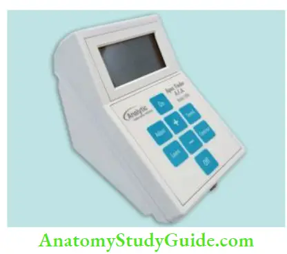
- Examples of fourth-generation apex locators are AFA apex finder, i-Pex, Rayapex 4, Propex, Elements Diagnostic Unit
The main problem with fourth-generation EALs is that they can perform well in relatively dry canals, so difficult to use in cases of heavy exudates or weeping canals.
5. Fifth-generation EALs (dual-frequency ratio type):
To overcome the disadvantages of previous generations of apex locators, fifth-generation EALs have been developed which are based on a comparison of data taken from the electrical characteristic of the canal and additional mathematical processing.
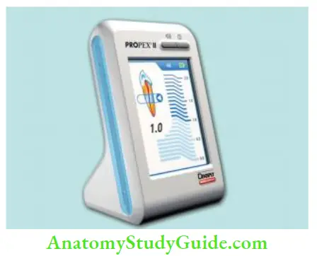
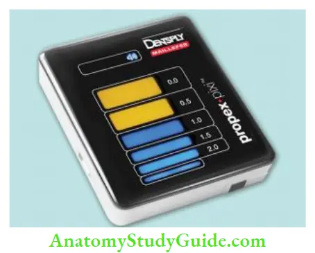
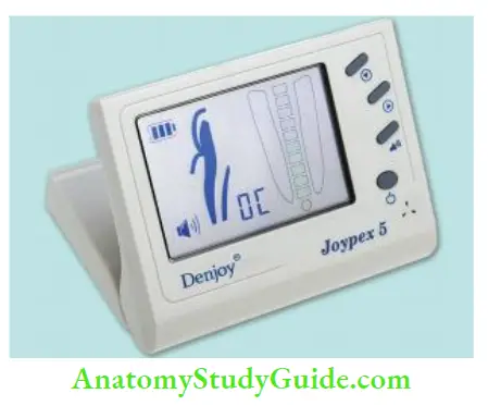
These show accurate readings in the presence of dry, wet, saline, EDTA, blood, or sodium hypochlorite. Examples of fifth-generation apex locators are Rayapex, Propex II, Propex Pixi, I -ROOT, Joypex 5
6. Sixth-generation EALs (adaptive apex locators):
This apex locator is intended to overcome the disadvantages of fourth- and fith-generation EALs. It eliminates the need of drying the canals. Examples of 6th generation apex locators are Adaptive apex locator, Raypex 6
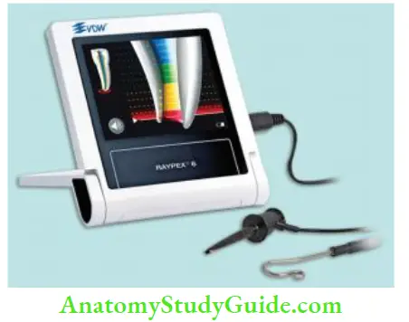
Combination of Apex Locators and Endodontic Handpiece:
Tri Auto ZX (J. Morita Calif) is a cordless electric endodontic handpiece with a built-in root ZX apex locator. It has three safety mechanisms:
- Autostart-stop mechanism: Handpiece starts rotation when the instrument enters the canal and stops when it is removed.
- Autotorque-reverse mechanism: Handpiece automatically stops and reverses rotation when the torque threshold exceeds. It prevents instrument breakage.
- Autoapical-reverse mechanism: It stops and reverses rotation when the instrument tip reaches a distance from apical constriction taken for working length. It prevents apical perforation. Endy 7000 reverses the rotation when the tip reaches the apical constriction. Sofy ZX (J. Morita Calif) uses Root ZX to electronically monitor the location of the fie tip during the entire instrumentation procedure.
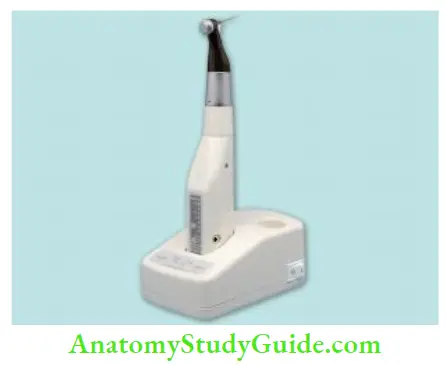
Basic Conditions for Accuracy of EALs:
- Whatever is the generation of the apex locator, there are some basic conditions, which ensure the accuracy of their usage.
- The canal should be free from most of the tissue and debris
- Apex locator works best in a relatively dry environment. But extremely dry canals may result in low readings, that is, long working length
- Cervical leakage must be eliminated and excess fluid must be removed from the chamber as this may cause inaccurate readings
- If residual fluid is present in the canal, it should be of low conductivity value, so that it does not interfere the functioning of the apex locator
- Descending the order of conductivity of various irrigating solutions is
- 5.25% NaOCl > 17% EDTA > saline
- Since EALs work on the basis of contact with canal walls and periapex. The better the adaptation of fie to the canal walls, the more accurate is the reading
- Canals should be free from any type of blockage, calcifications, etc.
- The battery of the apex locator and other connections should be proper
Working Length Determination Conclusion
Establishing a precise working length is mandatory for the success of the endodontic treatment. The cementodentinal junction (CDJ) is the anatomic point where instrumentation and obturation should end. Many techniques are available for the determination of accurate working length.
The CDJ, termination point for the preparation, and obturation of the root canal and this cannot be determined radiographically. Modern electronic apex locators can determine this position with accuracies of greater than 90% but still have some limitations.
Knowledge of apical anatomy, careful use of radiographs, and the correct use of an electronic apex locator will assist clinicians to achieve predictable results.
Leave a Reply